
Construction method for loop type hypobaric holes of railway tunnel

A tunnel and loop technology, applied in the field of construction of high-speed railway tunnel entrances, can solve problems such as limited use, longer distance and time for trains to pass through tunnels, and reduced ride comfort, so as to reduce pressure peaks and pressure gradients, and reduce air pressure. Dynamic effect, effect of increasing ride comfort

Inactive Publication Date: 2010-08-25
SOUTHWEST JIAOTONG UNIV
View PDF4 Cites 2 Cited by
  • Summary
  • Abstract
  • Description
  • Claims
  • Application Information

AI Technical Summary

Problems solved by technology

For extra-long tunnels, often due to the large buried depth, the shaft construction is difficult and costly, and this decompression method is difficult to popularize and use
2. Expand the cross-sectional area of ​​the tunnel and reduce the pressure by reducing the blocking ratio (the ratio of the cross-sectional area of ​​the train to the cross-sectional area of ​​the tunnel). Due to this method, the amount of tunnel construction has increased greatly, and its construction cost is high, so its use is also limited
3. To improve the airtightness of the rolling stock, this method can only improve the riding environment in the carriage and improve the comfort of passengers, but it cannot reduce the impact of high-speed trains on the environment outside the entrance
But this method actually increases the distance and time for the train to pass through the tunnel, reducing the comfort of the train

Method used


Image

  • Construction method for loop type hypobaric holes of railway tunnel
  • Construction method for loop type hypobaric holes of railway tunnel
  • Construction method for loop type hypobaric holes of railway tunnel

Examples


Embodiment

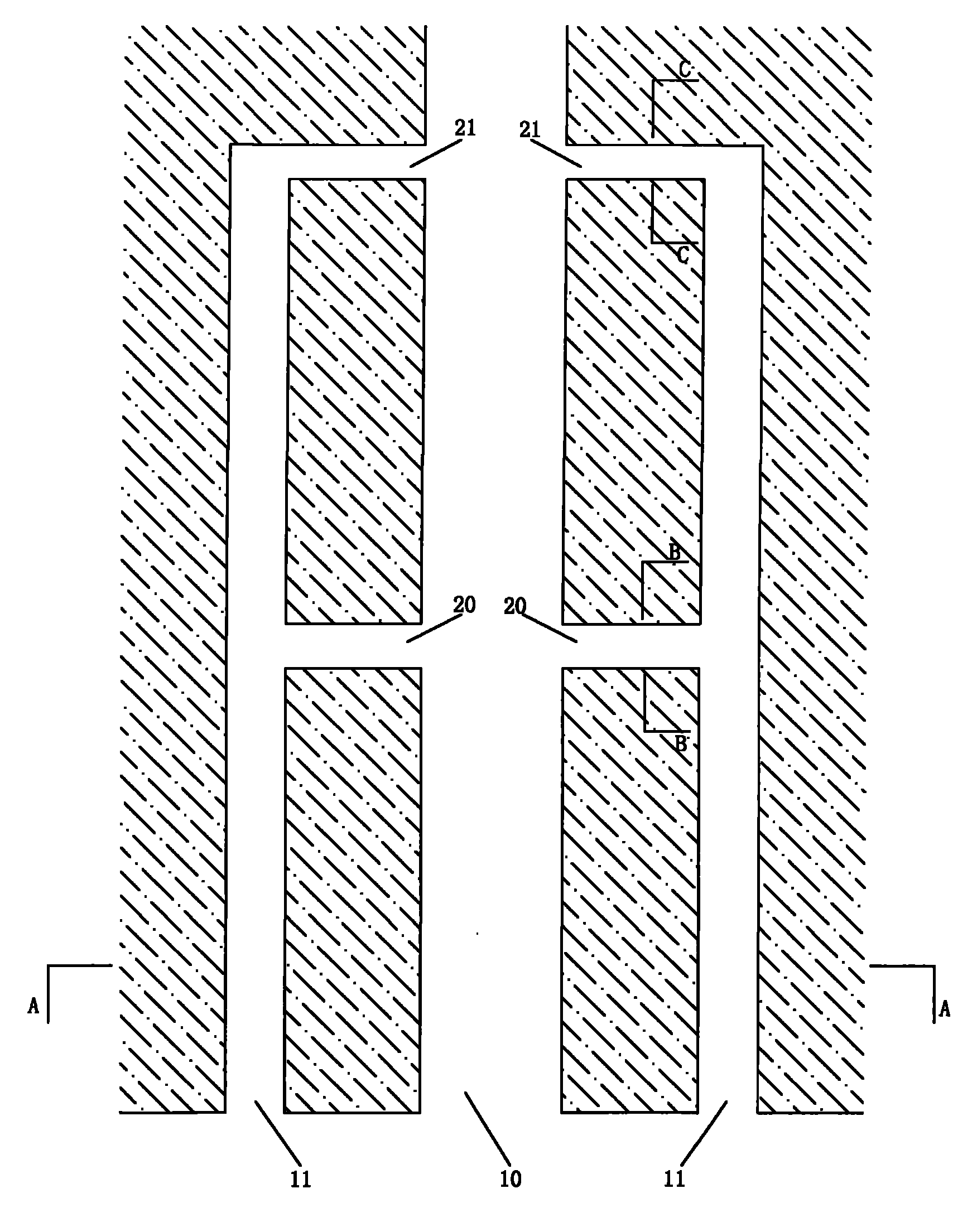
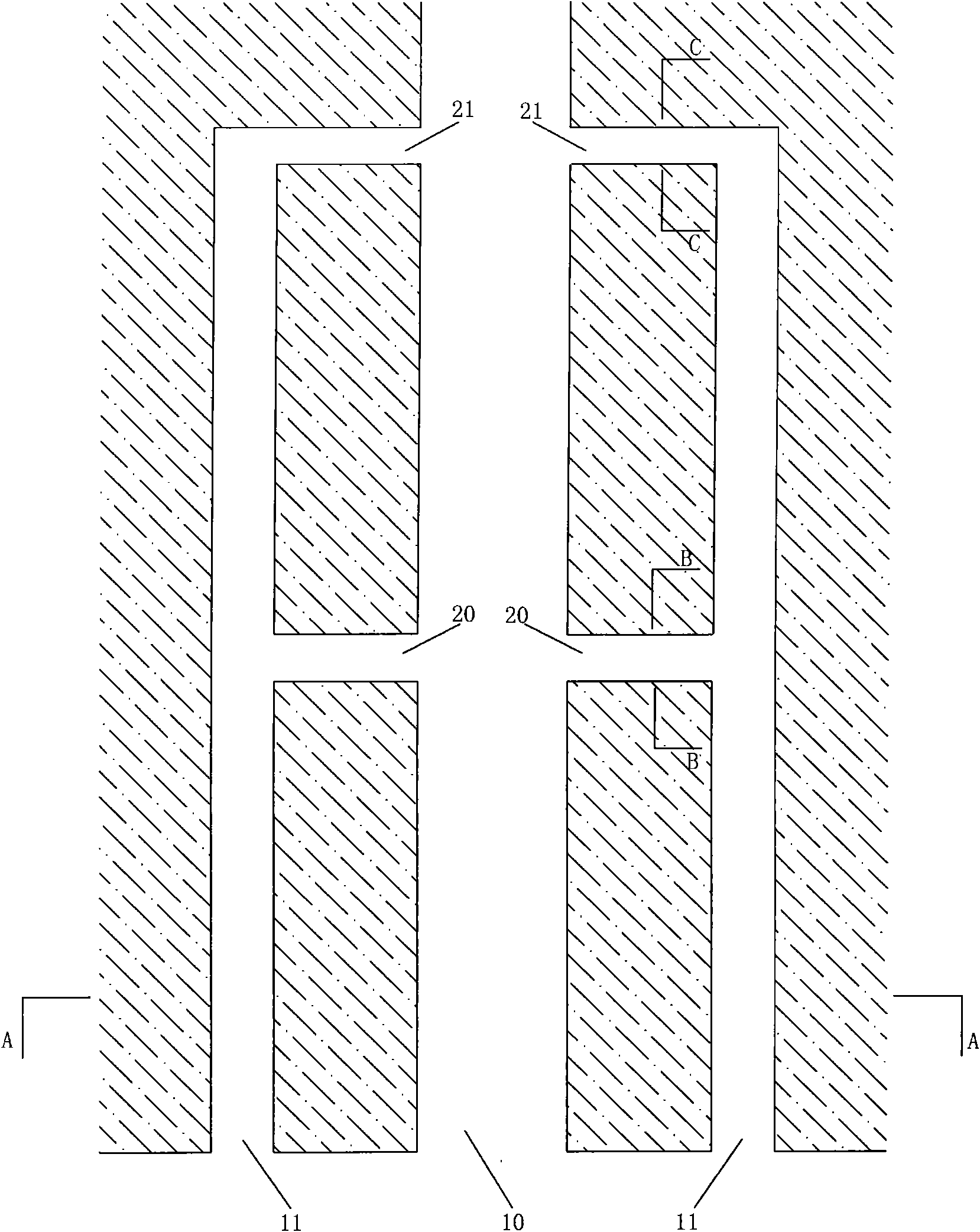
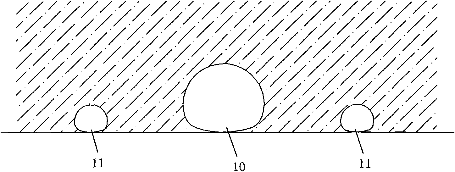
[0019] Fig. 1-4 shows, and a kind of embodiment of the present invention is, a kind of construction method of railway tunnel circuit type decompression hole, and its way is:

[0020] A. Build a side guide tunnel 11 parallel to the tunnel and having a length of 3.5-4.5 times the hydraulic diameter of the tunnel on both sides of the tunnel 10. The lateral distance between the side guide tunnel and the tunnel is 0.8-1.3 times the hydraulic diameter of the tunnel. The sectional area is 20%-30% of the tunnel sectional area;

[0021] B. Build two first and second cross passages 20, 21 between the guide tunnels on both sides and connect the side guide tunnels and tunnels. The first cross passage 20 is built at 1.5-2 times the tunnel hydraulic diameter from the tunnel entrance. , the sectional area is 10%-15% of the sectional area of ​​the tunnel; the second transverse channel 21 is connected with the inner end of the side guide tunnel, and the sectional area is 5%-10% of the sectiona...


PUM


Abstract

The invention discloses a construction method for loop type hypobaric holes of a railway tunnel. The method comprises the steps of A. constructing side leading holes (11) which are parallel to the tunnel and have lengths 3.5-4.5 times of the hydraulic diameter of the tunnel at the two sides of the hole of the tunnel (10), wherein the transverse distance of the side leading holes and the tunnel is 0.8-1.3 times of the hydraulic diameter of the tunnel, and the basal area of the side leading hole is 20 percent-30 percent of the basal area of the tunnel; B. constructing a first and a second cross passages (20, 21) transversely perforating the side leading holes and the tunnel between the two side leading holes, wherein the first cross passage (20) is constructed at the distance 1.5-2 times of the hydraulic diameter of the tunnel from the tunnel, and the basal area of the first cross passage is 10 percent-15 percent the basal area of the tunnel; and the second cross passage (21) is perforated with the inner ends of the side leading holes, and the basal area of the second cross passage is 5 percent-10 percent of the basal area of the tunnel. The micro-pressure wave phenomenon of the railway tunnel holes constructed by using the method is greatly reduced, the construction is easy and the construction cost is low.

Description

technical field [0001] The invention relates to a method for constructing a railway tunnel, in particular to a method for constructing an opening of a high-speed railway tunnel. Background technique [0002] When a train enters a railway tunnel at high speed, an initial compression wave will be generated in front of the train, and this wave will propagate forward along the tunnel. As the train further enters the tunnel and the length of the tunnel ring pipe continues to extend, the pressure in the tunnel also increases continuously, and the pressure before the peak of the compression wave also continues to increase until the trains have all entered the tunnel for a period of time. When the compression wave reaches the exit of the tunnel, it will be reflected to the entrance as an expansion wave. At the same time, a pulse wave will be generated to radiate from the exit of the tunnel to the surrounding area, making an explosion sound, and causing the window frames and shutters...

Claims


Application Information

Patent Timeline
IPC IPC(8): E21D9/14
Inventor 王英学高波周佳媚申玉生全晓娟赵文成贺旭洲张超付业凡刘佩斯韩华轩高玄涛孙向东
Owner SOUTHWEST JIAOTONG UNIV
Learn More