
A crankcase structure of internal-combustion engine

A technology for crankcases and internal combustion engines, applied to the cooling of engines, mechanical equipment, engine components, etc., which can solve problems such as thickening and increasing the weight of internal combustion engines, and achieve the effect of preventing expansion or contraction deformation and suppressing weight increase

Inactive Publication Date: 2012-03-14
HONDA MOTOR CO LTD
View PDF1 Cites 0 Cited by
  • Summary
  • Abstract
  • Description
  • Claims
  • Application Information

AI Technical Summary

Problems solved by technology

[0005] In order to ensure the rigidity and strength required for mounting and supporting the radiator at the opening end of the large opening of the cylindrical peripheral wall, the thickness of the cylindrical peripheral wall is increased to cope with the increase in the weight of the internal combustion engine.
[0006] In addition, when the internal combustion engine is supported on the vehicle frame via the engine hanger protruding from the crankcase, since it is necessary to ensure the strength of the root of the engine hanger where the force of the cylindrical peripheral wall of the crankcase is concentrated, the wall thickness of this part is increased. leading to a further increase in the weight of the internal combustion engine

Method used


Image

  • A crankcase structure of internal-combustion engine
  • A crankcase structure of internal-combustion engine
  • A crankcase structure of internal-combustion engine

Examples


Embodiment Construction

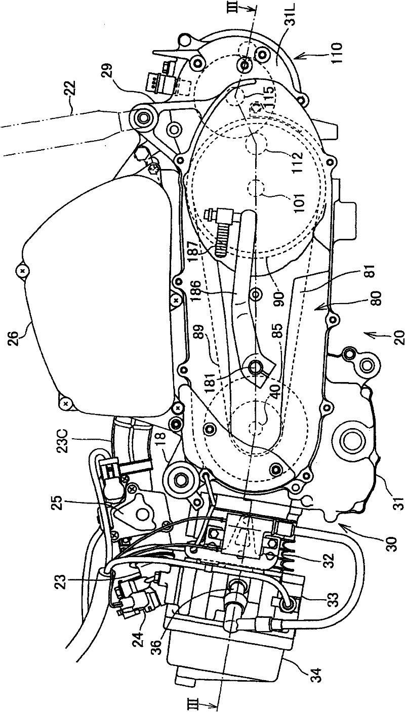
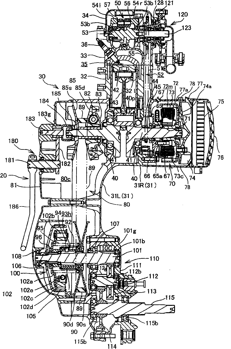
[0042] Below, based on Figure 1 to Figure 11 One embodiment of the present invention will be described.

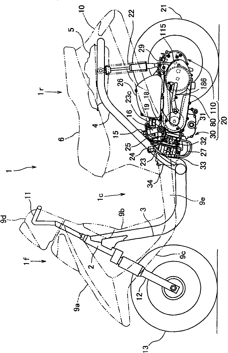
[0043] figure 1 It is a side view of a small motorcycle 1 to which one embodiment of the present invention is applied.

[0044] The front part 1f of the vehicle body and the rear part 1r of the vehicle body are connected via the low floor part 1c, and the frame constituting the skeleton of the vehicle body is generally composed of a downcomer 3 and a main pipe 4 .

[0045] That is, the downpipe 3 extends downward from the head pipe 2 of the vehicle body front part 1f, and the downpipe 3 is bent horizontally at the lower end and extends rearward under the floor portion 1c. 4. The main pipe 4 rises obliquely rearward from the connecting portion, bends horizontally at a predetermined height, and extends rearward.

[0046] A fuel tank 5 and the like are supported by the main pipe 4 , and a seat 6 is disposed above the fuel tank 5 .

[0047] On the other hand, in the vehic...


PUM


Abstract

This invention provides a crankcase structure of internal-combustion engine which can limit the thickness of the tubular walls of the crankcase and restrain the increase of the weight, ensure the needed rigidity and intensity at the same time. In crankcase structure of said internal-combustion engine, side walls (31Rw)of crankcase extends outside of the crankshaft to form tubular walls(31c), a case cover(77) covers the opening of the tubular walls(31c). Said crankcase structure of internal-combustion engine is supported by connecting the engine hanger(18) formed in the tubular walls(31c)with the frame, where the annular case strengthen part(78) that forms a annular shape along the opening end of the tubular walls(31c)and has thickness in radial direction is fixed on the opening end of thetubular walls(31c)by means of overlapping local part of the engine hanger(18).

Description

technical field [0001] The invention relates to a crankcase structure of an internal combustion engine. Background technique [0002] Various examples have been proposed for the crankcase structure of an internal combustion engine. For example, a crankcase in which a crankshaft of an internal combustion engine is pivotally supported by a side wall has a cylindrical peripheral wall extending from the side wall toward the outside in the direction of the crankshaft so as to surround an AC generator or the like. The AC generator is provided on a crankshaft protruding outward from a side wall (for example, refer to Patent Document 1). [0003] Patent Document 1: (Japanese) Unexamined Patent Publication No. 2005-233012 [0004] In this patent document 1, the AC generator is surrounded by a cylindrical peripheral wall extending from the side wall of the crankcase, and a radiator is mounted and supported on the opening end of the large opening. The radiator is arranged closer to th...

Claims


Application Information

Patent Timeline
Patent Type & Authority Patents(China)
IPC IPC(8): F02F7/00F01P3/04
CPCF21V11/08F21V19/0035F21V23/003F21W2121/00F21Y2105/18F21Y2115/10Y10S362/80
Inventor 堀井宣孝土屋粒二相原顺二佐藤和夫
Owner HONDA MOTOR CO LTD
Learn More