Liquid-filled vibration isolator

A vibration isolation, liquid technology, applied in the direction of shock absorber, shock absorber-spring combination, spring, etc., can solve the problem of limited space for engine support, and achieve the effect of improving comfort

Active Publication Date: 2010-08-25
KURASHIKI KAKO CO LTD
View PDF5 Cites 23 Cited by
  • Summary
  • Abstract
  • Description
  • Claims
  • Application Information

AI Technical Summary

Problems solved by technology

Moreover, there is a more basic problem, that is, the space in the engine mount is limited, and it cannot be sa...

Method used


Image

  • Liquid-filled vibration isolator
  • Liquid-filled vibration isolator
  • Liquid-filled vibration isolator

Examples


no. 1 approach

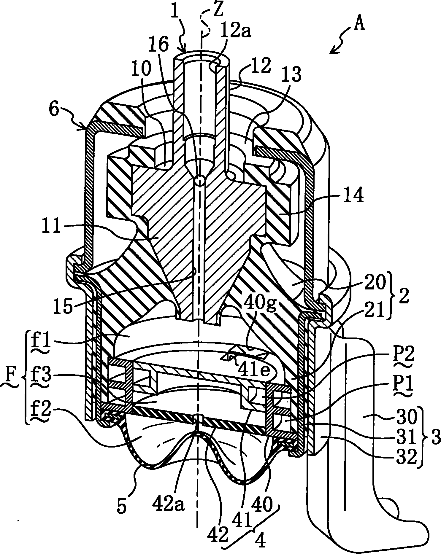
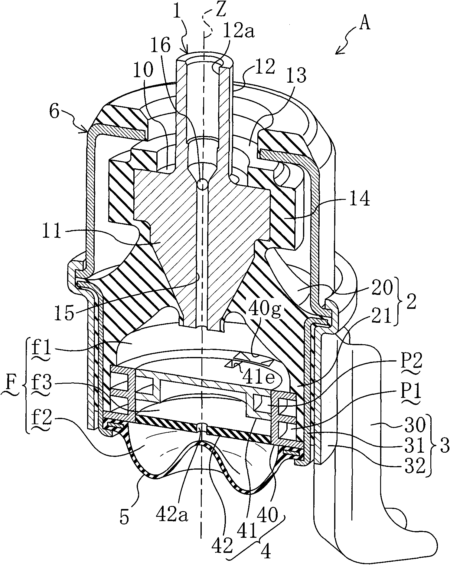
[0070] FIG. 1 shows an embodiment in which a liquid-filled vibration isolator according to the present invention is applied to an engine mount A for an automobile. The engine mount A is interposed between the engine and the transmission (hereinafter, the engine and the transmission are collectively referred to as a power plant) and the vehicle body, and is used to support the static load of these parts and absorb the The vibration of the power unit is damped or the vibration is damped to suppress transmission of the vibration to the vehicle body.

[0071] In addition, the engine mount A of the first embodiment includes an inner metal fitting 1 (first connecting metal fitting) and an outer metal fitting 3 (second connecting metal fitting), and the inner metal fitting 1 passes through a not-shown bracket or the like. Installed on the power unit, it is roughly columnar, and the outer metal part 3 supports the inner metal part 1 from below through the rubber elastic body 2, and is...

no. 3 approach and

[0120] (Third Embodiment and Modifications thereof)

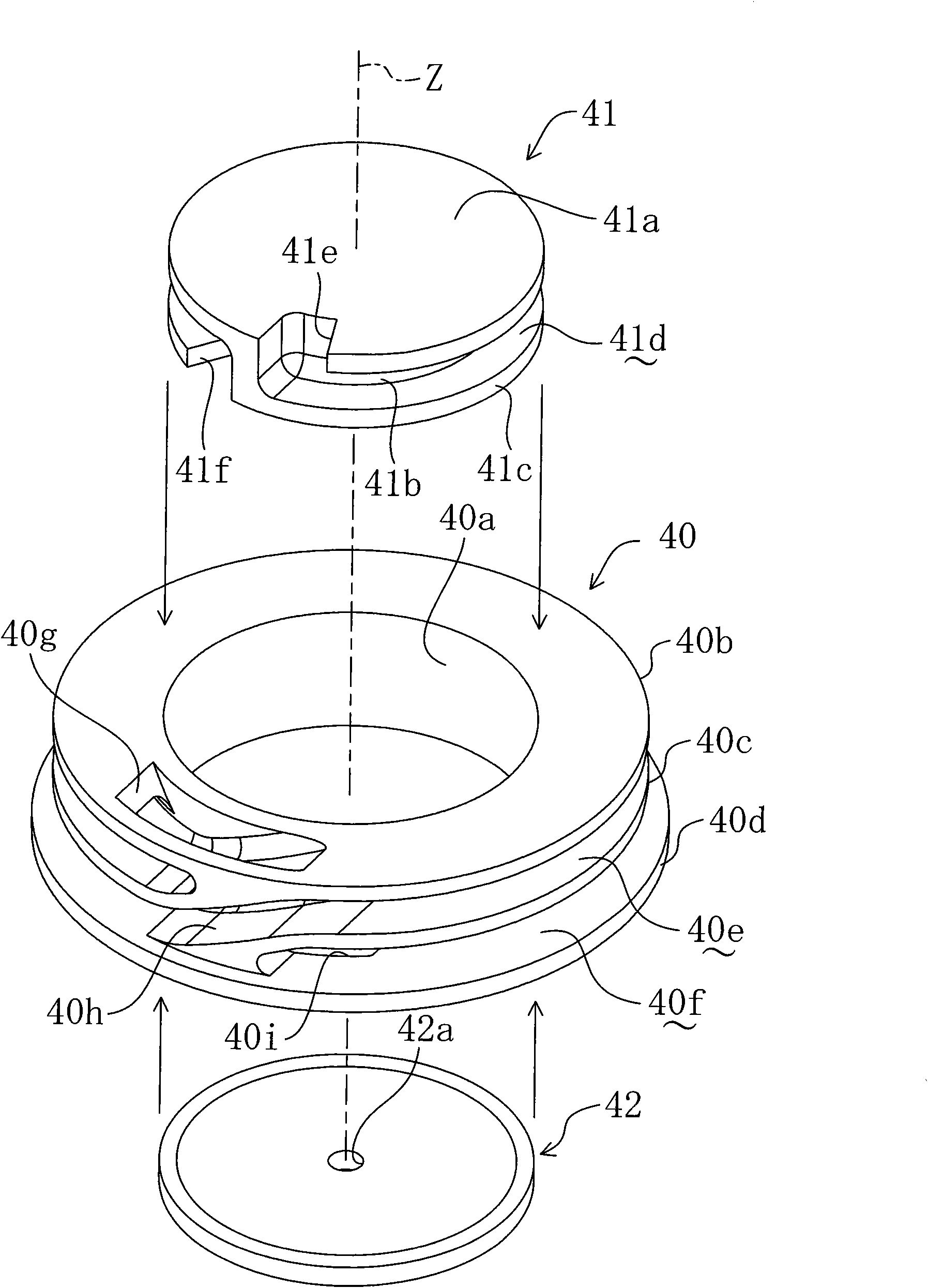
[0121] Next, an engine mount A according to a third embodiment of the present invention is shown in FIG. 15 . The support A is also the same, and the structure of the throttle plate 4 is different from that of the above-mentioned first embodiment and the like. That is to say, in the support A of the third embodiment, the throttle plate 4 is basically the same as the throttle plate 4 of the first embodiment, that is, an intermediate liquid chamber is provided on the side of the balance chamber f2 of the throttle plate 4 f3, the membrane 42 divides the two chambers f2, f3. In addition, a movable plate 43 is disposed on a partition wall between the intermediate liquid chamber f3 and the pressure receiving chamber f1.

[0122] That is, as shown enlarged in FIG. 16 , in the throttle plate 4 of the present embodiment, the inner member 41 is fitted from above into the inner side of the outer member 40 similar to the outer member...

no. 4 approach and

[0135] (Fourth Embodiment and Modifications thereof)

[0136] Finally, Fig. 22(a) to Fig. 22(c), Fig. 23(a) to Fig. 23(c) and Fig. 24(a) and Fig. 24(b) show the fourth embodiment of the present invention and its first to A longitudinal sectional view of an engine mount A' according to a seventh modification. These mounts A' generally have a structure as if the mounts A of the first to third embodiments and the like are reversed. Therefore, components having the same function even if they are different in shape or the like are denoted by the same symbols, and descriptions of these components are omitted.

[0137] The support A' of Fig. 22 (a) to Fig. 22 (c) corresponds to the support A of the first embodiment; the support A' of Fig. 23 (a) to Fig. 23 (c) corresponds to the second embodiment Support A. Specifically, the holder A' of Fig. 22(a) will be described. In this support A', the inner metal part 1 is connected to the vehicle body side (support side), and on the other ...


PUM

PropertyMeasurementUnit
Thicknessaaaaaaaaaa
Diameteraaaaaaaaaa
Thicknessaaaaaaaaaa

Abstract

The invention discloses a liquid-filled vibration isolator. The liquid-filled vibration isolator (A) has a first orifice channel (P1) providing communication between a pressure receiving chamber (f1) and a balancing chamber (f2). One of the pressure receiving chamber (f1) and the balancing chamber (f2) is communicated via a second orifice channel (P2) with an intermediate liquid chamber f3. The second orifice channel (P2) has a shorter distance or a larger cross-sectional area than the first orifice channel (P1). An elastic film member, such as a membrane (42), separates the intermediate liquid chamber (f3) and the other of the pressure receiving chamber (f1) and the balancing chamber (f2) from each other. A communicating hole (42a) of a predetermined size is formed in the elastic film member. An imaginary orifice channel combined from the two orifice channels (P1) and (P2) provides a high damping effect on input vibration of relatively low frequency. As the vibration frequency increases, a gradual transition is made to the damping characteristic of the second orifice channel (P2) only.

Description

technical field [0001] The present invention relates to a liquid-enclosed type vibration isolator for attenuating vibration by utilizing the flow resistance of liquid enclosed inside, and particularly relates to a structure of a liquid chamber and an orifice passage. Background technique [0002] Heretofore, an automotive engine mount is widely known as such a vibration isolator. The basic structure of an automobile engine mount is such that the first connecting metal part on the engine side (supported side) and the second connecting metal part on the vehicle body side (supporting side) are connected together by a rubber elastic body. , and a plurality of liquid chambers are formed between the two connecting metal parts in such a manner that the volume of the liquid chamber changes with the deformation of the rubber elastic body, and the plurality of liquid chambers are communicated with each other through a throttling passage. The engine vibration within a predetermined fr...

Claims


Application Information

Patent Timeline
IPC IPC(8): F16F13/10
CPCF16F13/107F16F13/106
Inventor 片山稔宫本尚规
Owner KURASHIKI KAKO CO LTD
Why Eureka
Try Eureka