Mechanism for mutual conversion between reciprocating motion and rotating motion, part and device thereof
A technology of reciprocating motion and rotary motion, applied to the mechanism that converts between reciprocating motion and rotary motion, and the components that make up the above mechanism
Active Publication Date: 2010-08-25
BEIJING SINOCEP ENGINE TECH
View PDF10 Cites 6 Cited by
- Summary
- Abstract
- Description
- Claims
- Application Information
AI Technical Summary
Problems solved by technology
In view of the above problems, the present invention provides a mechanism for mutual conversion between reciprocating motion and rotary motion. This mechanism does not need to use a circular slider, thereby solving various problems caused by the existence of a circular slider in the crank circular slider mechanism. At the same time, it can also Continue to retain the various advantages of canceling the connecting rod in the crank circular slider mechanism
Method used
View moreImage
Smart ImageViewing Examples

Examples
Embodiment 1
Embodiment 2
Login to View More PUM
 Abstract
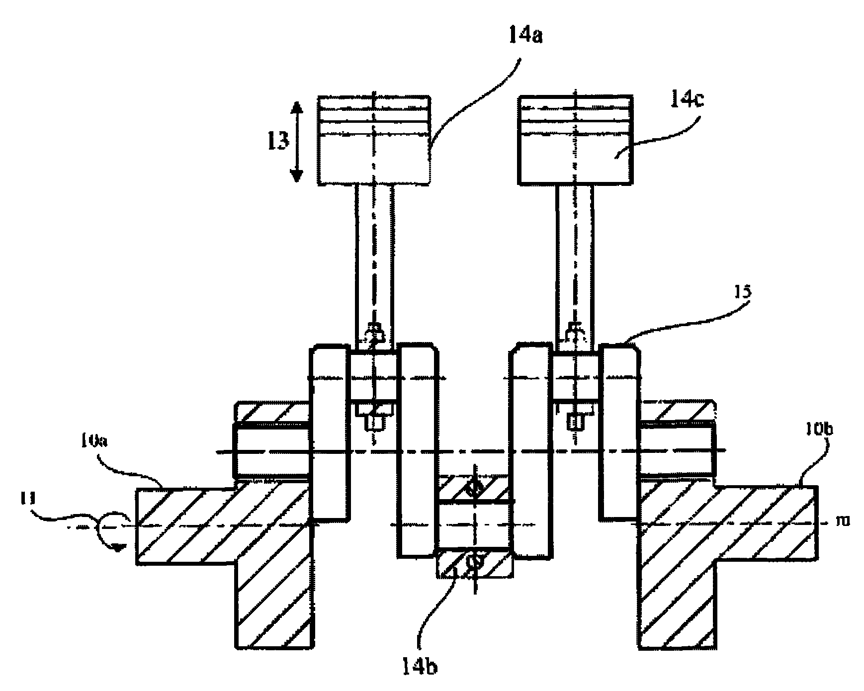
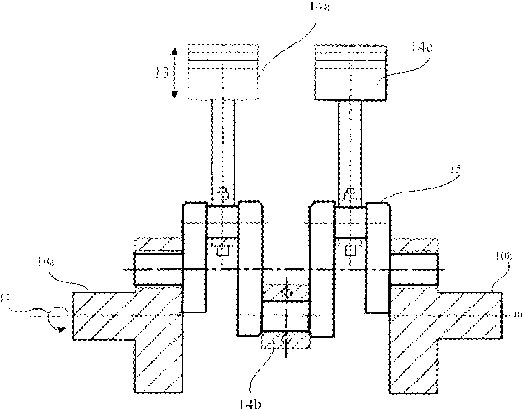
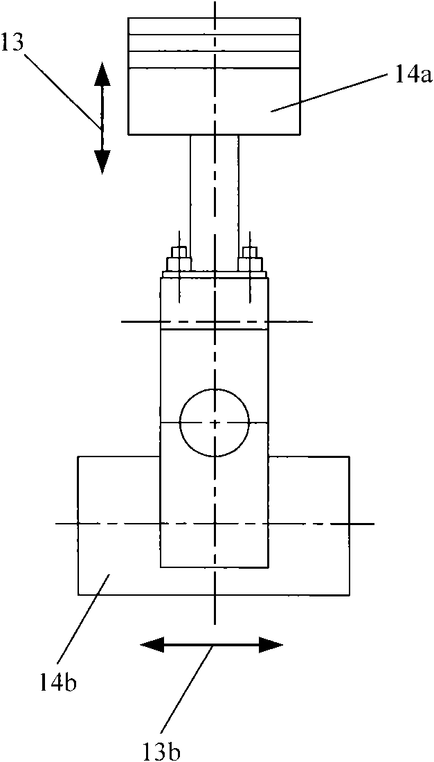
The invention relates to a mechanism for mutual conversion between reciprocating motion and rotating motion, which comprises a reciprocating motion part, a rotating motion part and a frame. The rotating motion part comprises two end shafts and a movable shaft. The end shafts can be rotatably fixed on the frame. The rotating shafts of the two end shafts are in one line. A movable shaft neck holding hole is arranged on each end shaft, wherein the distance from the axis of the movable shaft neck holding hole to the rotating shaft is e. Movable shaft necks are arranged at the two ends of the movable shaft. Three movable shaft pins are arranged in the middle, wherein the axis of the three movable shaft pins is in parallel with the axis of the movable shaft and the distance from the axis of the three movable shaft pins to the axis of the movable shaft is e. Phase difference of 180 degrees is kept for adjacent movable shaft pins in space. When in assembling, the movable shaft necks are respectively and rotatably connected with the movable shaft neck holding holes of the end shafts at the two ends. At least one reciprocating motion part placed in a reciprocating motion track is arranged corresponding to each movable shaft pin and is rotatably connected with the movable shaft pin through a movable shaft pin hole on the reciprocating motion part. Phase difference of 90 degrees is kept for the reciprocating motion tracks of the adjacent reciprocating motion parts in space. Since the mechanism has no connecting rod or circular sliding block, the defect caused by the connecting rod or the circular sliding block to the conversion mechanism is overcome. The invention additionally provides a device using the mechanism.
Description
Mechanisms and components and equipment for mutual conversion between reciprocating motion and rotary motion This application claims the priority of the Chinese patent application with application number 200910236026.5 submitted by the applicant on October 16, 2009. technical field The invention relates to a motion conversion mechanism, in particular to a mechanism for mutual conversion between reciprocating motion and rotary motion. The invention also relates to the components making up the mechanism described above, as well as to the equipment obtained using the mechanism described above. Background technique In mechanical equipment, it is necessary to realize mutual conversion between reciprocating motion and rotary motion in many occasions. For example, a reciprocating internal combustion engine needs to convert the reciprocating linear motion of the piston driven by the explosive pressure of the combustible mixture into the rotational motion of the crankshaft; on th...
Claims
Login to View More Application Information
Patent Timeline
 IPC IPC(8): F16H21/18F01B9/02F02B75/32F04B35/01
Inventor 黎明黎正中
Owner BEIJING SINOCEP ENGINE TECH
Features
- R&D
- Intellectual Property
- Life Sciences
- Materials
- Tech Scout
- Unparalleled Data Quality
- Higher Quality Content
- 60% Fewer Hallucinations
Learn More Browse by: Latest US Patents, China's latest patents, Technical Efficacy Thesaurus, Application Domain, Technology Topic, Popular Technical Reports.
© 2025 PatSnap. All rights reserved.Legal|Privacy policy|Modern Slavery Act Transparency Statement|Sitemap|About US| Contact US: help@patsnap.com