LED lamp structure

A technology of LED lamps and LED chips, which is applied to lighting devices, cooling/heating devices of lighting devices, light sources, etc., can solve problems such as increased costs, and achieve the effects of prolonging service life and reducing manufacturing costs

Inactive Publication Date: 2010-08-25
简孝伦
View PDF0 Cites 3 Cited by
  • Summary
  • Abstract
  • Description
  • Claims
  • Application Information

AI Technical Summary

Problems solved by technology

Because this kind of LED lamp structure 10 has several LEDs 12, and the package structure of each LED 12 needs to use a conductive frame 15, resulting in an increase in cost, it must be considered

Method used


Image

  • LED lamp structure
  • LED lamp structure
  • LED lamp structure

Examples


Embodiment Construction

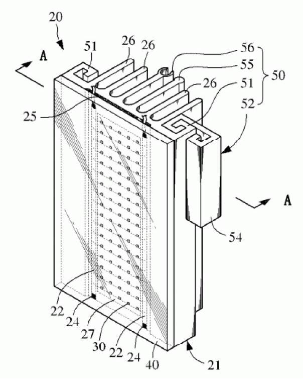
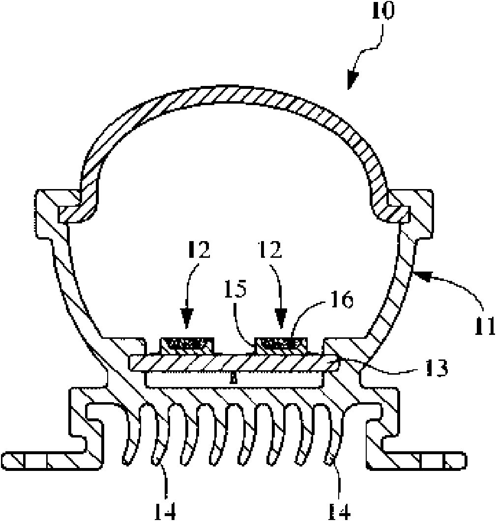
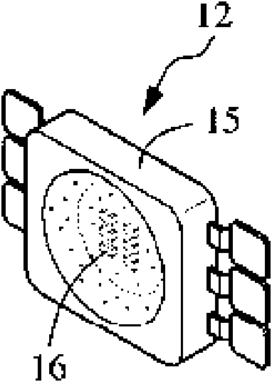
[0034] As shown in FIGS. 3 to 5 , the LED lamp structure 20 of the present invention includes a lamp body 21 , several LED chips 30 , a lampshade 40 and an extension structure 50 . The lamp body 21 is made of a material with better heat dissipation. The front end of the lamp body 21 is provided with a groove 23 , on which are provided a positive and negative conductive circuit 22 and a metal foil 27 , and the metal foil 27 is located between the positive and negative conductive circuit 22 . Several LED chips 30 are mounted on the metal foil 27, connected in series and parallel, and electrically connected to the positive and negative conductive lines 22 by wire bonding, so that the LED chips 30 and the connection point 24 are electrically connected, Finally, the encapsulation material 25 is filled on the groove 23 to complete the encapsulation, and the light source emitted by the LED chip 30 can be emitted through the encapsulation material 25 . Because the LED chip 30 is emit...


PUM


Abstract

The invention relates to an LED lamp structure which comprises a lamp body, a plurality of LED chips and a lamp shade, wherein the front end of the lamp body is provided with a groove, an anode and cathode conducting circuit and a metal foil, and the back end of the lamp body is provided with a plurality of cooling fins; the LED chips are loaded on the metal foil, electrically connected with the anode and cathode conducting circuit by a line throwing mode and also electrically connected with a wire connecting point, and finally, a packaging material is filled to complete packaging; and the lamp shade is arranged at the front end of the lamp body. The lamp structure not only can reduce power consumption and manufacturing cost, but also can prolong service life.

Description

Technical field: [0001] The invention relates to an LED lamp structure, in particular to a lamp structure capable of deriving the high temperature generated by the LED to eliminate the reduction of the luminous power of the LED due to overheating. Background technique: [0002] Light source is very important in daily life, no matter inside or outside the building, it must be illuminated by light source. However, the common light source is mainly fluorescent tubes. In order to obtain a good scattering effect of light, the lamps are usually installed at a higher position (such as the ceiling). Because the principle of fluorescent tubes is to use gas discharge, The accelerated movement of electrons in the fluorescent tube generates ultraviolet rays through the gas enclosed in the tube, and then emits light through the phosphor powder coated on the glass. Therefore, after the fluorescent lamp is used for about 6,000 hours, the mercury in the fluorescent tube has been eliminated....

Claims


Application Information

Patent Timeline
Patent Type & Authority Applications(China)
IPC IPC(8): F21S2/00F21V19/00F21V23/06F21V29/00F21Y101/02F21V29/74
Inventor 简孝伦
Owner 简孝伦
Why Eureka
Try Eureka