

Method utilizing polarization-controllable T-Hz wave to measure optical axis direction of birefringent crystal
A birefringent crystal and optical axis direction technology, applied in the direction of polarization influence characteristics, etc., can solve complex and time-consuming operations and other problems, and achieve the effect of simple and accurate measurement
Inactive Publication Date: 2010-08-25
CAPITAL NORMAL UNIVERSITY
View PDF0 Cites 20 Cited by
- Summary
- Abstract
- Description
- Claims
- Application Information
AI Technical Summary
Problems solved by technology
The present invention provides a method for measuring the optical axis direction of a birefringent crystal by using a polarization-controllable terahertz wave, so as to solve the problem in the above-mentioned background technology that the birefringent crystal needs to be rotated at least 180 degrees when measuring the optical axis of the birefringent crystal Carrying out measurements, technical issues that are not only time-consuming but also complex to operate in practical applications
Method used
View moreImage
Smart ImageViewing Examples

Examples
Embodiment Construction
Login to View More PUM
 Abstract
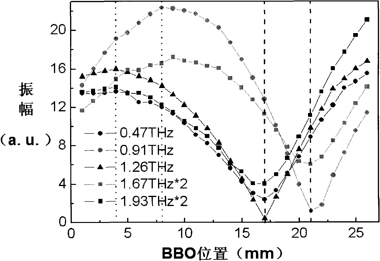
The method of the invention comprises the following steps: (1) moving a BBO crystal to change the distance from the BBO crystal to a plasma to obtain the relationship between the angle theta of the polarization direction of T-Hz wave relative to horizontal direction and the distance d from the BBO crystal to the plasma; (2) substituting the refractive indexes of T-Hz wave under different frequencies to a formula for calculating phase delay, thus obtaining the relationship of phase delay between the two axes of the birefringent crystal along with frequency change; (3) respectively selecting a corresponding T-Hz wave frequency f1 when the phase delay is odd times of pi and a corresponding T-Hz wave frequency f2 when the phase delay is even times of pi, moving the BBO crystal, and measuring the motion distance delta d of the BBO crystal corresponding to the T-Hz waves of frequency f1 and f2 at the nearest neighbor part with the minimum amplitude; and (4) calculating the included angle alpha between the birefringent crystal optical axis and the horizontal direction. Therefore, the invention can measure the optical axis direction of the birefringent crystal without rotating the birefringent crystal, thereby ensuring the measurement along the optical axis direction of the birefringent crystal to be more convenient and accurate.
Description
Method for Measuring the Optical Axis Direction of Birefringent Crystals Using Polarization-Controllable Terahertz Waves technical field The invention relates to a method for measuring the optical axis of a birefringent crystal, in particular to a method for measuring the direction of the optical axis of a birefringent crystal using a polarization-controllable terahertz wave spectrum. Background technique Due to its unique properties such as transient, low energy and coherence, terahertz radiation has great scientific value and broad application prospects in satellite communications, nondestructive testing, and military radar. Terahertz polarization measurement, terahertz communication, biomedical imaging, military target recognition, chemical composition analysis, and the production of terahertz filters all require precise control of the polarization direction of terahertz waves. By studying the polarization direction of the terahertz radiation generated by the excitatio...
Claims
Login to View More Application Information
Patent Timeline
 IPC IPC(8): G01N21/21
Inventor张亮亮钟华邓朝张存林
OwnerCAPITAL NORMAL UNIVERSITY