Composite phase change integrated cooling heat dissipation method and device for micro slot group of silicon controlled thyristor device
A technology of composite phase change and heat dissipation method, applied in electrical components, thyristors, electric solid devices, etc., can solve the problems of expensive, noisy, large functional space of thyristor power electronic equipment, etc.
- Summary
- Abstract
- Description
- Claims
- Application Information
AI Technical Summary
Problems solved by technology
Method used
Image
Examples
Embodiment 1
[0084] Below in conjunction with accompanying drawing and embodiment the present invention is described in detail:
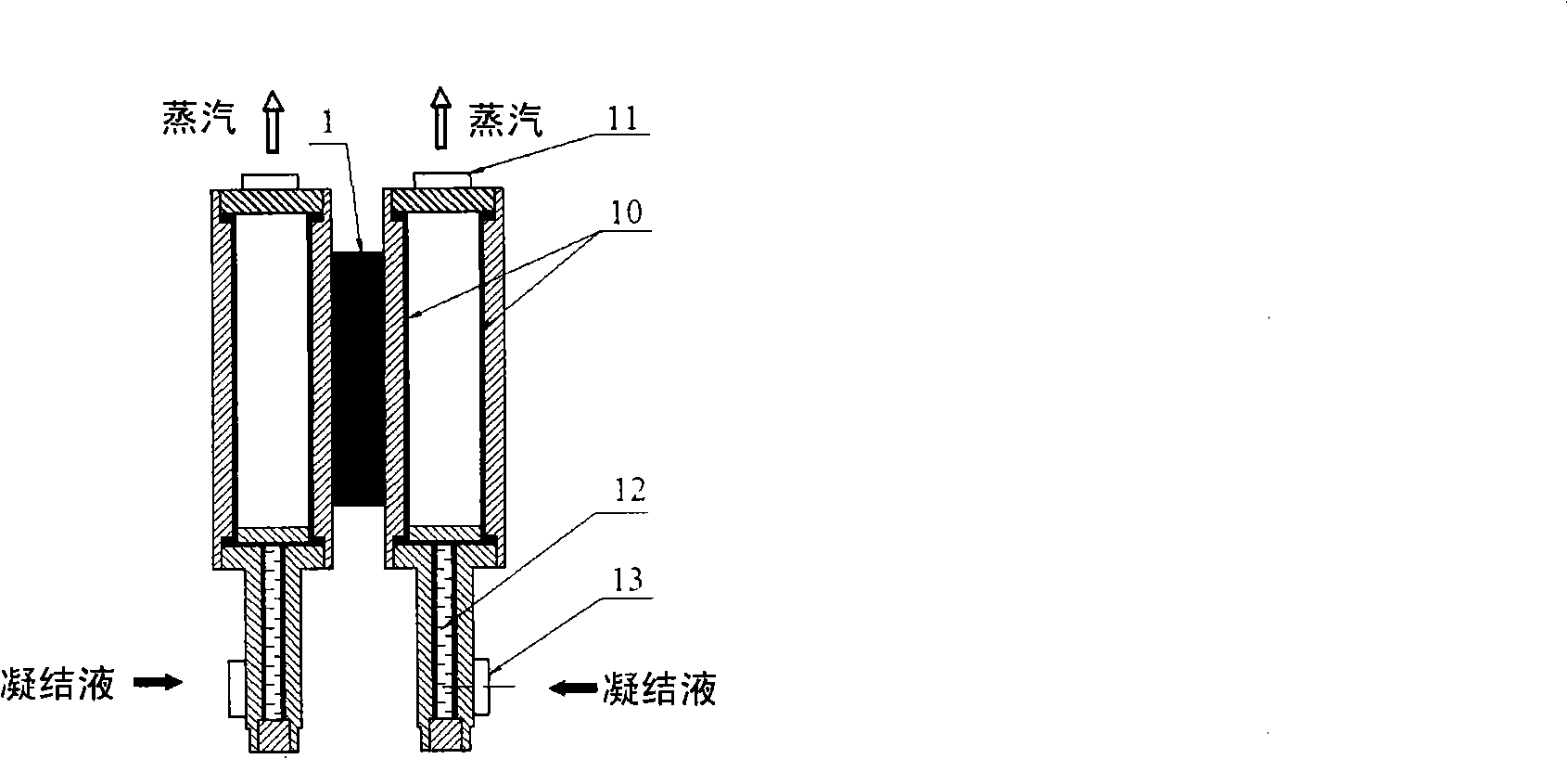
[0085] see Figure 4For the forced water-cooling mode micro-groove group composite phase change integrated cooling rectifier cooling system, for the power electronic equipment of the rectifier cabinet composed of 6 high-power thyristor components, a micro-groove of the thyristor device at the cold end of the forced water-cooling mode is produced Group composite phase change integrated cooling system. It includes a vacuumized micro-groove group composite phase-change heat collector 2 for taking heat from the heat-generating surfaces on both sides of the thyristor 1 . Each thyristor 1 is provided with two micro-groove composite phase-change heat extractors 2, each taking heat from one side of the thyristor 1. The 6 thyristors 1 forming the thyristor rectifier cabinet device are provided with 12 micro-groove composite phase-change heat extractors 2 in total. Each...
Embodiment 2
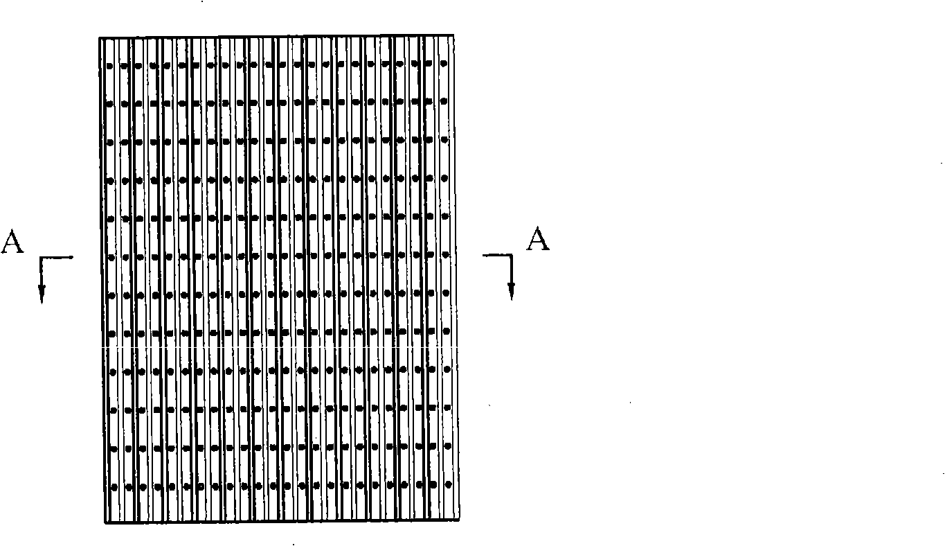
[0090] see Figure 5 For the forced air-cooling mode micro-groove group compound phase change integrated cooling rectifier cabinet heat dissipation system, for the rectifier cabinet power electronic equipment composed of 6 high-power thyristor components, a micro-groove of the thyristor device at the cold end of the forced air-cooling mode is produced Group complex phase change integrated cooling system. In Embodiment 1, the wall condenser 4 whose cold end is water-cooled mode is replaced with the wall condenser 4 whose cold end is air-cooled mode, as shown in FIG. 2b. The outer wall of the wall condenser 4 in air-cooled mode at the cold end is provided with vertical rectangular rib groups 22, the height of the rectangular fins is 10mm, the thickness of the fins is 2mm, and the spacing between the fins is 4mm; the cold end is in the air-cooled mode The wall condenser 4 is installed in the air duct away from the working space of the thyristor 1. Two fans 18 with a power of 50W...
Embodiment 3
[0092] see Figure 6 For the air natural convection mode micro-groove group composite phase change integrated cooling rectifier cabinet heat dissipation system, for the rectifier cabinet power electronic equipment composed of 6 high-power thyristor components, a kind of air natural convection mode cold-end thyristor device is produced Micro-groove group composite phase change integrated cooling and heat dissipation system. The wall condenser 4 adopts the wall condenser 4 in the air-cooled mode at the cold end in Embodiment 2, as shown in FIG. 2b. A vertical rectangular fin group 22 is arranged on the outer wall of the wall condenser 4 in the air-cooled mode at the cold end, the height of the rectangular fins is 20 mm, the thickness of the fins is 2 mm, and the spacing between the fins is 3 mm; the cold end is in the air-cooled mode The wall condenser 4 is installed in the external environment away from the working space of the thyristor 1, and the fan and air duct device in E...
PUM
| Property | Measurement | Unit |
|---|---|---|
| depth | aaaaa | aaaaa |
| thickness | aaaaa | aaaaa |
| height | aaaaa | aaaaa |
Abstract
Description
Claims
Application Information
 - R&D
- Intellectual Property
- Life Sciences
- Materials
- Tech Scout
- Unparalleled Data Quality
- Higher Quality Content
- 60% Fewer Hallucinations
Browse by: Latest US Patents, China's latest patents, Technical Efficacy Thesaurus, Application Domain, Technology Topic, Popular Technical Reports.
© 2025 PatSnap. All rights reserved.Legal|Privacy policy|Modern Slavery Act Transparency Statement|Sitemap|About US| Contact US: help@patsnap.com


