High-altitude lifesaving slow descender

A technology of slow descent device and speed controller, which is applied in life-saving equipment, building rescue and other directions, can solve the problems of poor stability, slow speed, inflexible control, etc., and achieves the effect of strong environmental applicability, convenient operation and simple structure.

Inactive Publication Date: 2010-09-01
HARBIN ENG UNIV
View PDF4 Cites 10 Cited by
  • Summary
  • Abstract
  • Description
  • Claims
  • Application Information

AI Technical Summary

Problems solved by technology

The existing life-saving descending devices have the disadvantages of slow speed, inflexible control, poor stability, etc., and there is no descending device realized by a gear mechanism and a hydraulic mechanism.
I

Method used


Image

  • High-altitude lifesaving slow descender
  • High-altitude lifesaving slow descender
  • High-altitude lifesaving slow descender

Examples


Embodiment Construction

[0020] The present invention is described in more detail below in conjunction with accompanying drawing example:

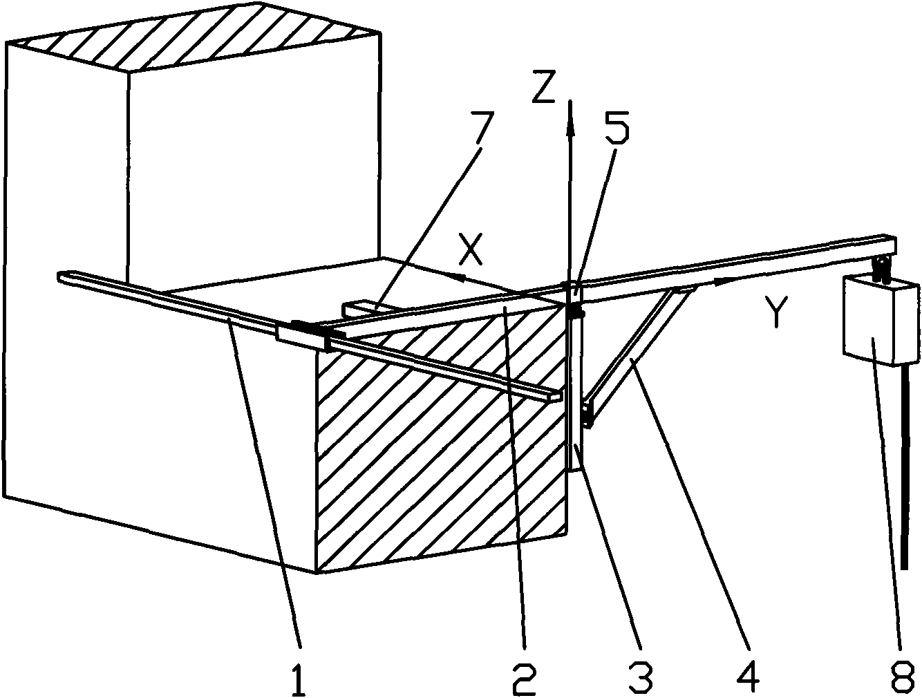
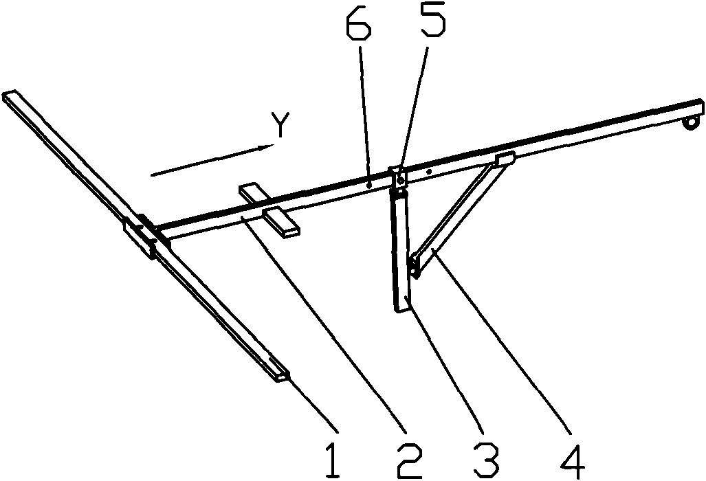
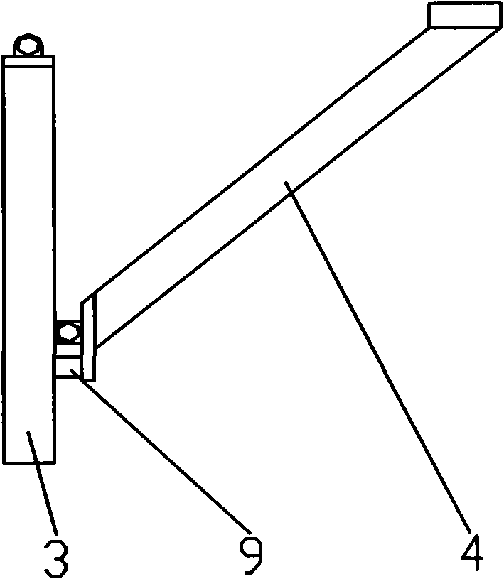
[0021] combine Figure 1-8 , the bracket is used to support the descending device to create better escape conditions for the user. The support is mainly composed of a cross bar 1, a cantilever beam 2, a vertical bar 3, a support bar 4, and a positioning sleeve 5. There are two positioning holes in the middle part of the cross bar 1. One end of the cantilever beam 2 is a square groove, and the crossbar 1 can be installed in the groove. The square groove has two holes corresponding to the positioning holes on the crossbar 2. When installing, use bolts to connect the crossbar 1 to the crossbar 2. The cantilever beam 2 is fixedly connected. The other end of the cantilever beam 2 has a ring to hang the descender. In addition, the side of the cantilever beam 2 is provided with a plurality of positioning holes 6 along the Y direction, which can realize the positionin...


PUM


Abstract

The invention aims to provide a high-altitude lifesaving slow descender comprising a safety support and a hydraulic slow decender, wherein the tail end of the safety support is installed with a circular ring, and the hydraulic slow decender is connected with the safety support through the circular ring. The safety support comprises a transverse bar, a cantilever beam, a vertical bar, a support bar, a positioning sleeve barrel, a short rod, the circular ring and a stop block, and the hydraulic slow decender comprises a speed controller and a rope wheel mechanism. The invention has the advantages of simple structure, convenient operation, strong applicability to environment as well as safety and reliability.

Description

technical field [0001] The invention relates to a mechanical device, in particular to a mechanical device applied to lifesaving. Background technique [0002] With the acceleration of the urbanization process, there are more and more high-rise buildings. When unexpected disasters such as fires and earthquakes occur in high-rise buildings, how to make the trapped people escape to a safe area quickly and safely has received increasing attention. From the perspective of portability, rapidity and safety, the descending device is an ideal self-rescue device. The existing life-saving descending devices have the disadvantages of slow speed, inflexible control, poor stability, etc., and there is no descending device realized jointly by a gear mechanism and a hydraulic mechanism. In the past, the descending device needs to be fixed on the wall before use or the holes required for assembly must be reserved on the wall, which is not conducive to rescue at high altitude in an emergency...

Claims


Application Information

Patent Timeline
IPC IPC(8): A62B1/06A62B1/12A62B1/18
Inventor 王玉甲段清柱石先杰苏浩陆玉婷
Owner HARBIN ENG UNIV
Why Eureka
Try Eureka