Cavity die rotating upsetter and operating method thereof
A technology of upsetting forging machine and die, which is applied to upsetting forging presses, forging presses, forging presses, etc., can solve the problems of reducing upsetting forging efficiency, no ejector needle, and complex reset structure, and achieves easy and fast upsetting forging, The effect of improving work efficiency
- Summary
- Abstract
- Description
- Claims
- Application Information
AI Technical Summary
Problems solved by technology
Method used
Image
Examples
Embodiment 1
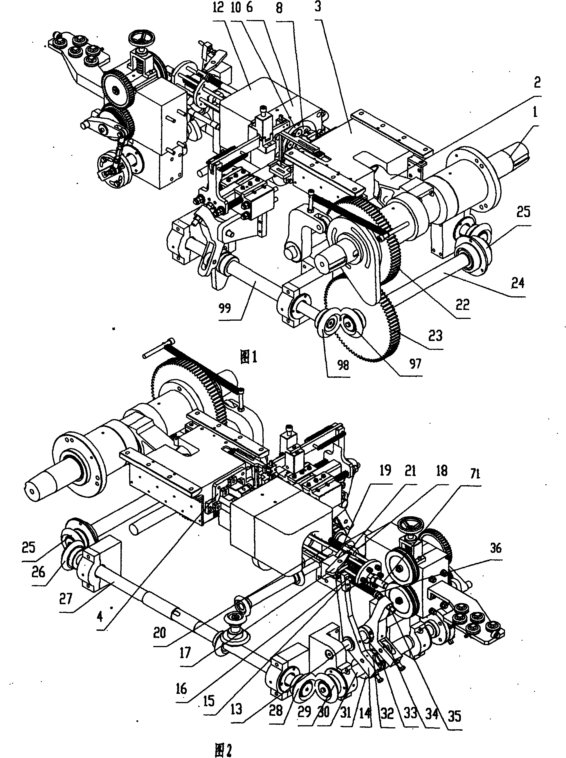
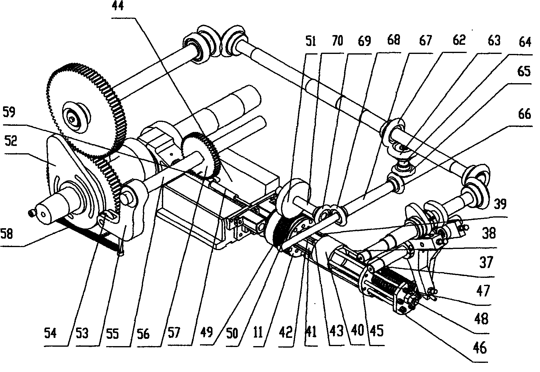
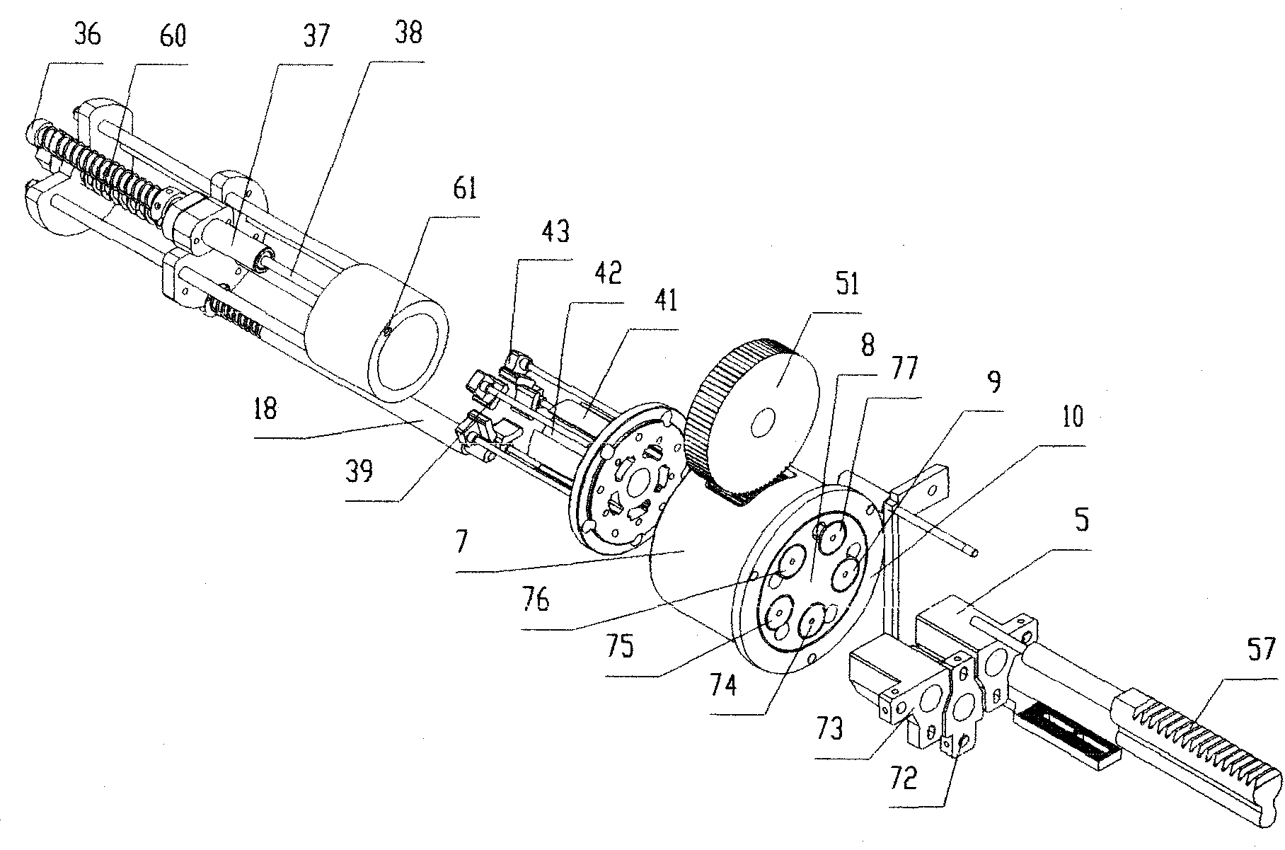
[0026] Such as Figure 1 to Figure 4 As shown, a die rotary upsetting machine includes a die assembly, a drive mechanism for the die assembly that moves the die assembly back and forth relative to the die assembly, a die assembly, and a material cutting and clamping mechanism, which are only set at the discharge position The workpiece ejection mechanism, the die indexing device that makes the die rotate at a set angle, the die positioning device that stops the die at the set position, and the ejector mechanism.
[0027] The driving mechanism of the die assembly includes a crankshaft 1, a connecting rod 2 mounted on the crankshaft 1, and a large slider 3 pivotally connected to the connecting rod 2 in a rotatable manner. Die assembly comprises the die backing plate 4 that is fixed on the large slide block 3, and three dies that are evenly fixed on the die backing plate 4 are punching die 5, punching die 72, and punching die 73.
[0028] The die assembly includes a die holder 6 ...
Embodiment 2
[0053] Such as Image 6 As shown, the difference from Embodiment 1 is that the thimble stopper adjustment mechanism includes a second bolt 100 and a stopper 102; a guide hole (not shown) for the thimble stopper is provided on the body, and the thimble The limit stopper 103 is provided with a detent plane 106 for preventing the thimble limit resister 103 from rotating relative to the body and an escape hole (not shown) for the second bolt 100. Plane (not shown), thimble stopper 103 and guide hole gap fit; One end of the second bolt 100 away from the die base 104 is the rotating clamping hexagon head end 101, and the second bolt 100 is close to the rotating clamping hexagonal head The end 101 is provided with a limit boss 107, and the end of the second bolt 100 close to the die base 104 is a threaded end; the limit sleeve 102 is fixed with the body, and the limit sleeve 102 is provided with the second bolt 100 and the limit boss. Cooperating stepped holes, the large hole 108 of...
PUM
 Abstract
Description
Claims
Application Information
 - R&D
- Intellectual Property
- Life Sciences
- Materials
- Tech Scout
- Unparalleled Data Quality
- Higher Quality Content
- 60% Fewer Hallucinations
Browse by: Latest US Patents, China's latest patents, Technical Efficacy Thesaurus, Application Domain, Technology Topic, Popular Technical Reports.
© 2025 PatSnap. All rights reserved.Legal|Privacy policy|Modern Slavery Act Transparency Statement|Sitemap|About US| Contact US: help@patsnap.com


