
Cavity die rotating upsetter and operating method thereof

A technology of upsetting forging machine and die, which is applied in upsetting forging presses, forging presses, forging presses, etc., can solve the problems of reduced upsetting forging efficiency, no ejector pin, complex reset structure, etc., and achieves easy and fast upsetting forging, The effect of improving work efficiency

Inactive Publication Date: 2012-03-07
杨东佐
View PDF1 Cites 0 Cited by
  • Summary
  • Abstract
  • Description
  • Claims
  • Application Information

AI Technical Summary

Problems solved by technology

When this type of upsetting machine is to realize high-speed upsetting, since the ejector pin needs to be separated from the die base when the die base rotates, on the one hand, it is necessary to provide an ejector pin reset mechanism that separates the ejector pin from the die base. , so that the structure of the upsetting machine is complicated; on the other hand, the length of the ejector pin is long, and the ejector pin must be continuously in and out of the die seat, and the ejector pin is easily damaged. For example, a compression spring reset device is used between the ejector pin and the die seat. It is easy to be damaged, which shortens the service life of the upsetting machine, and other reset structures will become particularly complicated; especially when high-speed upsetting is required, the ejector pin must repeatedly enter the die seat and be separated from the die seat. For the forging cycle, it takes a long time, so the upsetting efficiency is greatly reduced
The invention patent with the patent number ZL87105260.1 does not have a reset mechanism for the ejector pin. Judging from the published text and drawings, it cannot realize the separation of the ejector pin from the die base, and the die base will be blocked when it rotates. The ejector pin is blocked, so the rotation of the die base cannot be realized, and the technical solution of this patent cannot be realized, so it can be proved that the technical solution has not been actually implemented

Method used


Image

  • Cavity die rotating upsetter and operating method thereof
  • Cavity die rotating upsetter and operating method thereof
  • Cavity die rotating upsetter and operating method thereof

Examples


Embodiment 1

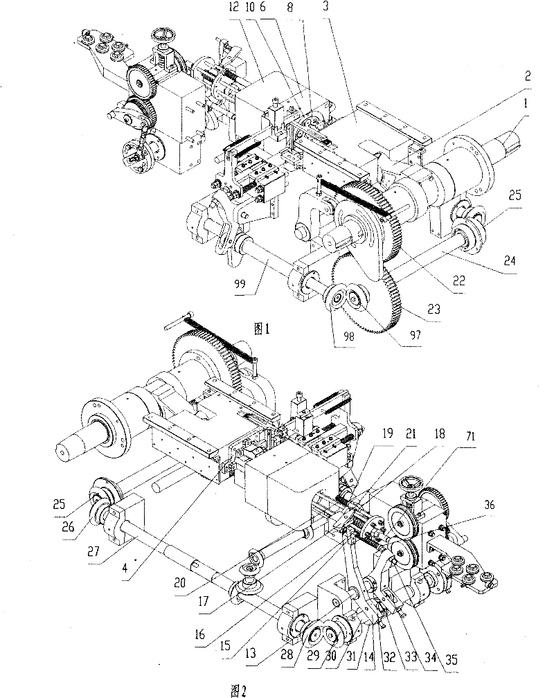
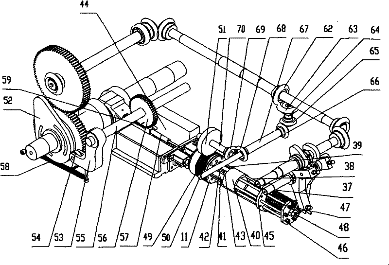
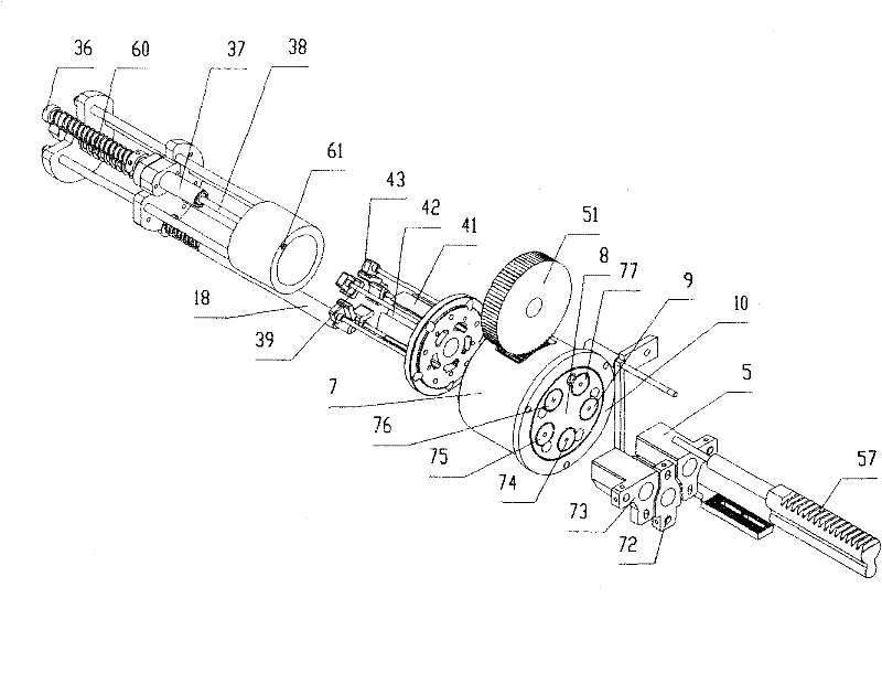
[0026] Such as Figure 1 to Figure 4 As shown, a die rotary upsetting machine includes a die assembly, a drive mechanism for the die assembly that moves the die assembly back and forth relative to the die assembly, a die assembly, and a material cutting and clamping mechanism, which are only set at the discharge position The workpiece ejection mechanism, the die indexing device that makes the die rotate at a set angle, the die positioning device that stops the die at the set position, and the ejector mechanism.

[0027] The driving mechanism of the die assembly includes a crankshaft 1, a connecting rod 2 mounted on the crankshaft 1, and a large slider 3 pivotally connected to the connecting rod 2 in a rotatable manner. Die assembly comprises the die backing plate 4 that is fixed on the large slide block 3, and three dies that are evenly fixed on the die backing plate 4 are punching die 5, punching die 72, and punching die 73.

[0028] The die assembly includes a die holder 6 ...

Embodiment 2

[0053] Such as Figure 6 As shown, the difference from Embodiment 1 is that the thimble stopper adjustment mechanism includes a second bolt 100 and a stopper 102; a guide hole (not shown) for the thimble stopper is provided on the body, and the thimble The limit stopper 103 is provided with a detent plane 106 for preventing the thimble limit resister 103 from rotating relative to the body and an escape hole (not shown) for the second bolt 100. Plane (not shown), thimble stopper 103 and guide hole gap fit; One end of the second bolt 100 away from the die base 104 is the rotating clamping hexagon head end 101, and the second bolt 100 is close to the rotating clamping hexagonal head The end 101 is provided with a limit boss 107, and the end of the second bolt 100 close to the die base 104 is a threaded end; the limit sleeve 102 is fixed with the body, and the limit sleeve 102 is provided with the second bolt 100 and the limit boss. Cooperating stepped holes, the large hole 108 o...


PUM


Abstract

The invention relates to a cavity die rotating upsetter and an operating method thereof. The upsetter comprises a rotatable cavity die holder, cavity dies uniformly distributed in the cavity die holder, a guide post fixed with the cavity die holder, a sliding chute arranged in the guide post, a friction slider installed in the sliding chute, a thimble spacing stopper fixed on the upsetter body and a thimble spacing stopper adjusting mechanism; a workpiece ejector mechanism is arranged only in a position from which a workpiece is ejected out of the cavity die, and the workpiece ejector mechanism comprises a ejector rod which can eject a thimble; and a position, which is corresponding to the ejector rod, on the thimble spacing stopper is provided with a clearance hole. The operating method comprises the following steps: in the rotating process of the cavity die holder, the thimble and the cavity die holder rotate synchronously, the thimble keeps stationary relative to the cavity die holder, and the thimble stopper does not move. The invention has the advantages that the workpiece ejector mechanism only needs to be arranged in the discharging position, and particularly, the thimble does not need to be separated from the cavity die holder in the rotating process of the cavity die holder, thereby facilitating the high-speed upsetting and improving the operating efficiency.

Description

technical field [0001] The invention relates to a rotary upsetting machine for dies and a working method thereof, in particular to a rotary upsetting machine for dies and a working method for forming standard parts such as fasteners at high speed. Background technique [0002] In existing upsetting machines, the die is generally fixed to the machine body, and the transposition between processes is realized by clamping the blank from one die to another die by the back and forth movement of the punch or clamping mechanism such as clamps. This kind of upsetting machine has a complex structure, and it is particularly difficult to realize high-speed upsetting. In order to solve the problem of high-speed upsetting, the invention patent No. ZL87105260.1 discloses a multi-station die rotary high-speed upsetting machine, which provides at least three dies on the rotary die base , the slider should be equipped with the same number of dies corresponding to the dies of the die base; th...

Claims


Application Information

Patent Timeline
Patent Type & Authority Patents(China)
IPC IPC(8): B21J9/06B21J13/02B21J13/08
CPCB21J9/06B21G3/12B21J9/022B21J13/14
Inventor 杨东佐
Owner 杨东佐
Learn More