Combined intelligent monitoring bearing

An intelligent monitoring and combined technology, applied in the field of bearings, can solve the problems of signal transmission intermediate interface reduction, bearing stress concentration, stress concentration, etc., to improve reliability and effectiveness, reduce bearing stress concentration, and facilitate installation and disassembly Effect

Active Publication Date: 2011-08-17
CHONGQING UNIV
View PDF5 Cites 0 Cited by
  • Summary
  • Abstract
  • Description
  • Claims
  • Application Information

AI Technical Summary

Problems solved by technology

The external combination method does not destroy the structure of the bearing but changes the overall size of the traditional bearing. At the same time, the characteristics of this type of combination determine that there is a certain distance between the sensing component and the source of the fault, so that the acquired signal cannot truly reflect the bearing. This method cannot be used for early detection of bearing fault characteristics, because the bearing fault detection with this structure cannot guarantee the reliability of the signal; the embedded combination method is very close to the source of the measured signal, and the signal The intermediate interface of transmission is reduced, the collected signal can truly reflect the actual working condition of the bearing, and the signal-to-noise ratio is high, but this structure destroys the integrity of the bearing, and it is easy to cause problems such as stress concentration, so this structure is also important for bearing state detection. there are certain problems
[0003] The disadvantages of the existing technology are: there is a certain distance between the external structure sensing component and the fault source, the obtained signal cannot truly reflect the fault information of the bearing, and the embedded structure destroys the internal structure of the bearing, causing the stress of the bearing concentration problem

Method used


Image

  • Combined intelligent monitoring bearing
  • Combined intelligent monitoring bearing
  • Combined intelligent monitoring bearing

Examples


Embodiment Construction

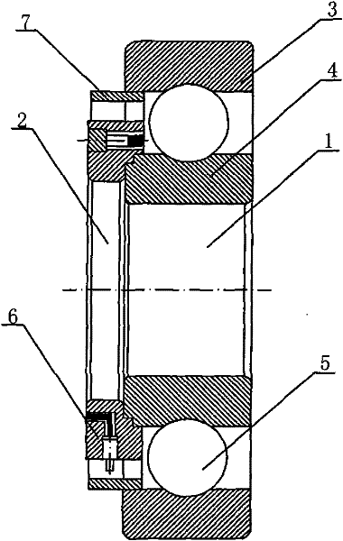
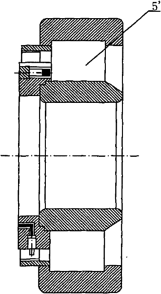
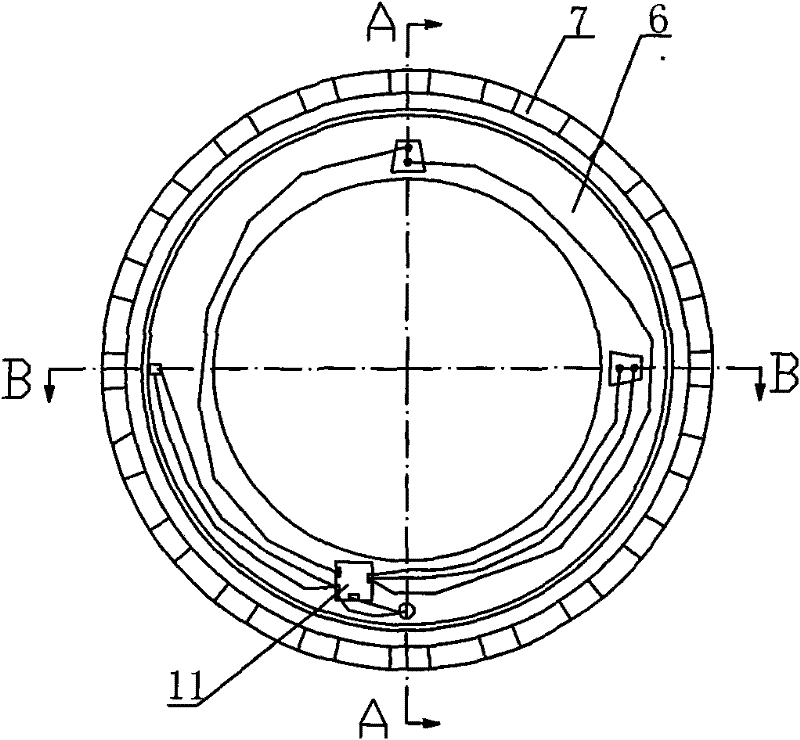
[0033] like figure 1 and 2As shown, a combined intelligent monitoring bearing includes a bearing 1 and an intelligent monitor 2 installed on the bearing. The bearing 1 includes a rotating outer ring 3 and a fixed inner ring 4. Balls 5 or rollers 5' are arranged between the moving inner rings 4. The smart monitor 2 includes a housing 6 and a speed code disc 7. The speed code disc 7 is set outside the housing 6 and connected to the housing 6. A concentric circular code disc, the intelligent monitor 2 is axially inserted into the gap between the rotating outer ring 3 and the immovable inner ring 4 of the bearing 1 to interfere with the bearing, wherein the rotational speed code disc 7 is in interference fit with the inner wall of the rotating outer ring 3, an annular step is provided on the butt end surface of the outer wall of the stationary inner ring 4, and a groove matching the annular step is provided on the butt end surface of the inner wall of the housing 6, The annular ...


PUM


Abstract

The invention discloses a combined intelligent monitoring bearing, which comprises a bearing (1) and an intelligent monitor (2) arranged on the bearing. The bearing (1) comprises a rotary outer ring (3) and a fixed inner ring (4); and a ball (5) or roller (5') is arranged between the rotary outer ring (3) and the fixed inner ring (4). The combined intelligent monitoring bearing is characterized in that the intelligent monitor (2) comprises a shell (6) and a rotation speed code disc (7) which is sleeved outside the shell (6) and is coaxial with the shell (6); the intelligent monitor (2) is axially inserted in a gap between the rotary outer ring (3) and the fixed inner ring (4) of the bearing (1) to be in interference fit with the bearing. The combined intelligent monitoring bearing has theadvantages of realizing short-distance detection of fault information of the bearing without damaging the bearing structure, truly achieving the acceleration, rotation speed and temperature for the work of the bearing without damaging the structure of the bearing or causing stress concentration of the bearing.

Description

technical field [0001] The invention belongs to bearings, in particular to a novel combined intelligent monitoring bearing applied to bearing state detection. Background technique [0002] The current integrated smart bearings have two structural forms: external and embedded. The external combination method does not destroy the structure of the bearing but changes the overall size of the traditional bearing. At the same time, the characteristics of this type of combination determine that there is a certain distance between the sensing component and the source of the fault, so that the acquired signal cannot truly reflect the bearing. This method cannot be used for early detection of bearing fault characteristics, because the bearing fault detection with this structure cannot guarantee the reliability of the signal; the embedded combination method is very close to the source of the measured signal, and the signal The intermediate interface of transmission is reduced, the col...

Claims


Application Information

Patent Timeline
Patent Type & Authority Patents(China)
IPC IPC(8): G01M13/04G01P3/44G01P15/08G01K13/08
Inventor 邵毅敏李小侠孙婷婷李杰周平周晓君陈再刚王辉
Owner CHONGQING UNIV
Why Eureka
Try Eureka