Rolling bearing and cage for such bearing

A rolling bearing and cage technology, applied in the field of rolling bearings, can solve problems such as high acceleration, unsuitable for high speed, fragile impact, etc.

Active Publication Date: 2010-09-01
AB SKF
View PDF1 Cites 5 Cited by
  • Summary
  • Abstract
  • Description
  • Claims
  • Application Information

AI Technical Summary

Problems solved by technology

Such cages are expensive and not suitable for high speeds and high accelerations due to inertia due to their solid construction
Furthermore, constructing such a cage from carbon makes it relatively brittle and sensitive to impact

Method used


Image

  • Rolling bearing and cage for such bearing
  • Rolling bearing and cage for such bearing
  • Rolling bearing and cage for such bearing

Examples


Embodiment Construction

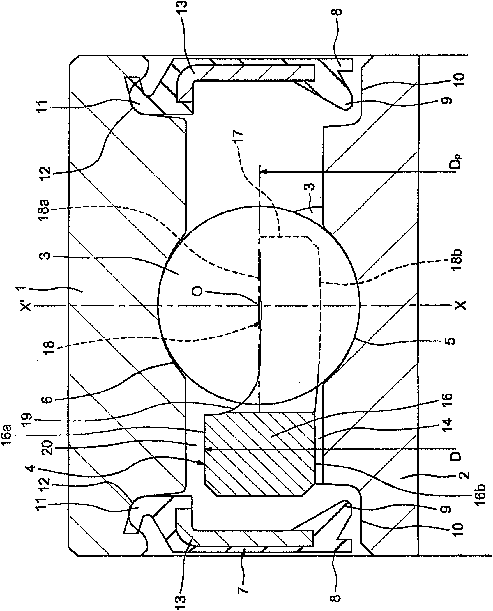
[0034] First refer to figure 1 , the rolling bearing shown, which is shown in a stationary state or rotating at a low speed, without deformation due to centrifugal force, includes an outer race 1 and an inner race 2 . Between the two races 1 , 2 is mounted a row of balls 3 held by a cage 4 of annular general shape. The balls 3 roll on ring-shaped deep bearing tracks formed in the outer surface 5 of the inner race 2 and in the bore 6 of the outer race 1 respectively. The rolling bearings are protected from external impacts by seals 7 on both sides, said seals having a generally annular plate shape with two sealing lips 8 and 9 on the bore side, which in operation form a narrow passage between them and a cylindrical surface 10 which is an integral part of the inner race 2 and whose outer diameter is smaller than that of the inner race 2 . The outer periphery of each seal 7 has a resilient edge 11 capable of snapping into a groove 12 formed in the sides of the bore of the outer...


PUM


Abstract

Retaining cage for balls of a rolling bearing, comprising an annular shoulder (16) extended axially by projecting portions (18) definingbetween them sockets (15) for the balls, emerging radially on either side of the cage. The cage was made from a metal and the surface of each socket (15) is designed to cooperate with one of the balls and is defined by an imaginary cylinder with an axis oriented radially and cut by the plane axially delimitingthe cage on the side opposite the shoulder (16) so as to form an axial opening of the socket, the width of this opening being smaller than the diameter of the said imaginary cylinder.

Description

technical field [0001] The present invention relates to rolling bearings, especially ball bearings of the deep groove type, which are used in high-speed rotating and high-temperature applications. In particular, the invention relates to ball cages that provide correct circumferential spacing between balls. Background technique [0002] Ball cages for rolling bearings made of synthetic material are known which comprise sockets for housing the balls. The sockets are separated by pairs of claws positioned opposite the shoulders. Such a cage is completely satisfactory in many cases. However, cages of this type lead to problems where very high velocities and accelerations associated with high operating temperatures are encountered. This is the case, for example, for multi-plate clutches and for racing cars of the F1 type. With the clutch engaged, both races of the bearing turn at the same speed and in the same direction on the order of 19,000 rpm. Then, there is no relative ...

Claims


Application Information

Patent Timeline
Patent Type & Authority Applications(China)
IPC IPC(8): F16C33/41
CPCF16C33/445F16C19/06F16C33/44F16C2204/12F16C2204/10F16C33/414
Inventor 弗朗西斯·克劳德阿梅尔·L·多耶亚历山大·曼塞厄让-玛丽·格拉德艾伯托·弗拉
Owner AB SKF
Why Eureka
Try Eureka