Three-blade concave face ball-tooth dill bit applicable to self-drilling type hollow anchoring system

An anchoring system and self-drilling technology, which is applied in construction and other fields, can solve the problems of lower drilling efficiency, side teeth slipping, lack of drill bits, etc., and achieve the effect of improving cleaning effect, wide cutting range and good cutting effect

Inactive Publication Date: 2017-05-31
洛阳恒诺锚固技术有限公司
View PDF5 Cites 1 Cited by
  • Summary
  • Abstract
  • Description
  • Claims
  • Application Information

AI Technical Summary

Problems solved by technology

In the application of marl, chalk, gravel, and weak mudstone, due to the high drilling efficiency, there is a lack of a drill bit with a good centering effect. During the drilling process, the drill bit is easy to deviate from the established line, causing the rod body to bend and affect the drill bit. Support performance and effect
For ball tooth all-steel drill bits, the wear speed of the side teeth is twice that of the internal ball teeth, and the side teeth are prone to wear first and slip, reducing drilling efficiency, etc.

Method used


Image

  • Three-blade concave face ball-tooth dill bit applicable to self-drilling type hollow anchoring system
  • Three-blade concave face ball-tooth dill bit applicable to self-drilling type hollow anchoring system
  • Three-blade concave face ball-tooth dill bit applicable to self-drilling type hollow anchoring system

Examples


Embodiment 1

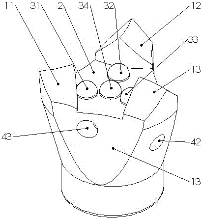
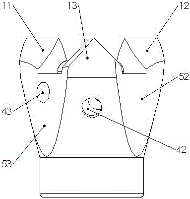
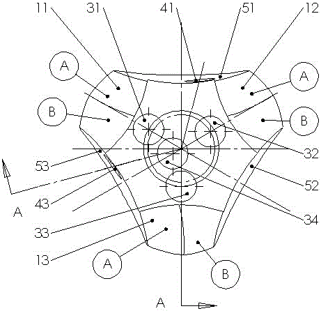
[0037] like Figure 1-4 As shown, the three-edged concave button drill bit suitable for the self-drilling hollow anchor system of the present invention includes two parts, the head and the trouser body. The head is provided with three cutting edges, a lower groove 2 and 4 button teeth distributed in the lower groove 2 . There are three arc-shaped chip removal grooves evenly distributed on the outer wall of the trousers, which are used for chip removal during drilling; the first water outlet hole 41 and the second water outlet hole 43 are distributed in the chip removal groove, and the outer wall of the trousers is provided with 1 water hole 42, used for passing pressure water, flushing cuttings and cooling drill bit cutting edge. There is a threaded cavity inside the trouser body, which can be screwed with the external thread of the self-drilling rod body, and realizes the energy transmission required for drilling, and communicates with the water hole 42 through the internal ...


PUM


Abstract

The invention provides three-blade concave face ball-tooth dill bit applicable to a self-drilling type hollow anchoring system and belongs to full-steel drill bits. Three cutting edges which are not mutually connected, a lower groove located in the middle of the drill bit and four ball teeth distributed in the lower groove are installed on the head portion; the directions of the two main cutting edges are the same, the main cutting edges are sunken towards the rotating direction, and the vice cutting edge is sunken towards the direction opposite to the rotating direction; one main cutting edge and the vice cutting edge are mutually symmetrical relative to the bisecting surface of an arc scrap discharging groove between the two cutting edges, a water outlet hole is distributed in the two scrap discharging grooves correspondingly, and water passing holes are formed in the outer wall of the drill bit below the main cutting edge adjacent to a scrap discharging groove without a water outlet hole; and distribution of three outer ring s ball teeth is the same as that of the cutting edges, and the center of the fourth ball tooth is located nearby the center of the lower groove. According to the three-blade concave face ball-tooth dill bit applicable to the self-drilling type hollow anchoring system, through work division of the three cutting edges, overall drilling efficiency is high, and design of the lower groove enables the precision of a finished hole to be promoted; and the water outlet holes and the water passing holes are arranged correspondingly, so that while rocks, soil and the cutting edges are effectively wetted by pressure water, direct reverse impacting of the pressure water and scraps of the rocks and the soil is avoided.

Description

technical field [0001] The invention relates to a drill bit for geological engineering, in particular to a three-edged concave button drill bit suitable for a self-drilling hollow anchor system. Background technique [0002] With the strengthening of water conservancy, energy, transportation, mining, and urban infrastructure, the application of bolt support in tunnels and slopes is becoming more and more extensive. Bolt support makes full use of the self-stabilizing ability of rock mass. Especially the self-drilling hollow bolt system can quickly form holes and inject grout, which can ensure the support force (prestress) immediately after the excavation of the rock mass, prevent the deformation and loosening of the surrounding rock, and enhance the stability of geotechnical engineering sex. [0003] There are many drill bits in the self-drilling bolt system, and the commonly used ones are "one", "ten" and button-toothed, each of which has its own characteristics. Accordin...

Claims


Application Information

Patent Timeline
Patent Type & Authority Applications(China)
IPC IPC(8): E21B10/43
CPCE21B10/43
Inventor 许岩波李子向杜景景牛翔张丰霞肖盼盼
Owner 洛阳恒诺锚固技术有限公司
Why Eureka
Try Eureka