
Wire stripping machine

A stripping machine and wire technology, applied in the installation of circuits, electrical components, cables, etc., can solve problems such as labor and achieve the effect of small radial deformation

Active Publication Date: 2020-08-14
SUZHOU LEMIFUN ELECTRICAL TECH CO LTD
View PDF5 Cites 2 Cited by
  • Summary
  • Abstract
  • Description
  • Claims
  • Application Information

AI Technical Summary

Problems solved by technology

[0003] The invention provides a wire stripping machine, which solves the laborious problem of manually cutting the wire insulation sleeve with a knife

Method used

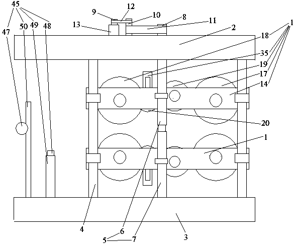
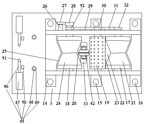
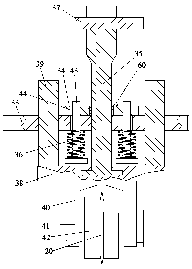

Image

  • Wire stripping machine
  • Wire stripping machine
  • Wire stripping machine

Examples


Embodiment Construction

[0025] The present invention will be further described below in conjunction with the accompanying drawings and embodiments.

[0026] see figure 1 , figure 2 with image 3 , a wire stripping machine, including a frame, a driving mechanism and two cutting and conveying modules 1 distributed along the up and down direction. The frame includes a top board 2 and a bottom board 3 . The top board and the bottom board are connected together by four vertical guide posts 4 . The four vertical guide posts are distributed in a quadrilateral shape. Two screw mandrels 5 distributed along the front and rear directions are also arranged between the top plate and the bottom plate. Screw mandrel comprises upper half section 6 and lower half section 7. The thread direction of the upper half is opposite to that of the lower half. The lower end of the lower half is rotatably connected to the base plate. The upper end of the first half is rotatably connected to the top plate. A driven synch...


PUM


Abstract

The invention relates to a wire stripping machine. The machine comprises two sectioning conveying modules distributed in the vertical direction. Each sectioning conveying module comprises a connectingbase, a sectioning knife assembly, a feeding side positioning wheel and a feeding wheel. The sectioning knife assembly comprises a circular cutting blade, the feeding side positioning wheel comprisestwo feeding side positioning wheel part conical sections of which the small-diameter ends are in butt joint together, a feeding side positioning wheel part positioning ring groove is defined betweenthe two feeding side positioning wheel parts, and the circular cutting blade is aligned with the feeding side positioning wheel part positioning ring groove; the positioning ring grooves of the feeding side positioning wheel parts of the two sectioning conveying modules are aligned, and the feeding wheels of the two sectioning conveying modules clamp an electric wire to drive the electric wire totranslate; a plurality of power-assisted spikes used for piercing into a wire insulation sleeve are arranged on the circumferential surface of the feeding wheel, and the vertex angles of the conical sections of the two feeding side positioning wheel parts are equal. The wire stripping machine has the advantage of being capable of sectioning the electric wire insulation sleeve, and the problem thatlabor is wasted when a knife is manually used for slitting the electric wire insulation sleeve is solved.

Description

technical field [0001] The invention relates to the technical field of electric appliance construction and waste product recycling, in particular to a wire stripping machine. Background technique [0002] The electric wire is composed of a wire conductive core of a metal structure and a wire insulating sleeve of an insulating structure wrapped outside the conductive core of the wire. In the process of electric power construction or waste recycling, it is necessary to peel off the wire insulation sleeve of the wire (some of them peel off a section of a wire, and some of the wire insulation sleeve on the entire wire is peeled off). Since the wire strippers are only suitable for stripping short lengths of the power supply, when the existing long length or overall stripping of the wire insulation sleeve is performed manually with a knife, the wire insulation sleeve is cut and then torn off, and the wire insulation sleeve is manually cut. There is laborious deficiency in cover. ...

Claims


Application Information

Patent Timeline
Patent Type & Authority Applications(China)
IPC IPC(8): H02G1/12H01B15/00H01R43/28
CPCH01B15/006H01R43/28H02G1/1248H02G1/126H02G1/127Y02W30/82
Inventor 郑伟哲
Owner SUZHOU LEMIFUN ELECTRICAL TECH CO LTD
Learn More