
A kind of anchor for carbon fiber parallel cable and its anchoring method

An anchoring method, carbon fiber technology, applied in construction, building reinforcements, bridge construction, etc., can solve the problems of rod body damage anchorage efficiency, uneven stress distribution in the anchorage area, etc., to increase anchorage efficiency, improve anchorage efficiency, and reduce stress concentrated effect

Active Publication Date: 2022-06-28
UNIV OF SCI & TECH BEIJING +1
View PDF7 Cites 1 Cited by
  • Summary
  • Abstract
  • Description
  • Claims
  • Application Information

AI Technical Summary

Problems solved by technology

[0006] The present invention is to solve the technical problem of the existing CFRP cable anchorage system, which is caused by the uneven stress distribution in the anchorage area, which leads to the failure of the rod body and the low anchorage efficiency. It provides an anchor for carbon fiber parallel cables and its anchoring method.

Method used


Image

  • A kind of anchor for carbon fiber parallel cable and its anchoring method
  • A kind of anchor for carbon fiber parallel cable and its anchoring method

Examples


Embodiment 1

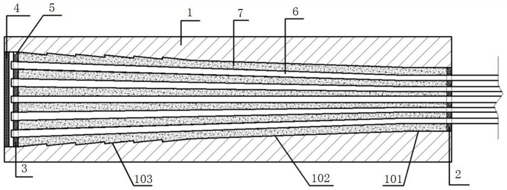
[0028] Embodiment 1. An anchor for carbon fiber parallel cables in this embodiment includes an anchor cup 1, a front-end wire dividing plate 2, a rear-end wire dividing plate 3, and a sealing bolt 4. The sealing bolt 4 is connected to the anchor cup 1. The inner diameter of the rear end is threaded, and the anchor cup 1 is an integral structure composed of a front straight section 101, a middle straight cone section 102 and a rear triangular groove section 103. The inner cavity of the front straight section 101 is cylindrical. The inner cavity of the middle straight cone section 102 is in the shape of a truncated cone, the inner cavity of the rear end triangular groove section 103 is in the shape of a tower-shaped truncated cone, and one end of the rear end wire dividing plate 3 is connected with the inner cavity of the anchor cup 1 The exhaust hole 5 of the rear end triangular groove section 103, the angle between the truncated truncated busbar and the axis of each layer of th...

Embodiment 2

[0029] Embodiment 2. The method of anchoring the carbon fiber parallel cable with the anchor of embodiment 1 is carried out according to the following steps:

[0030] Step 1: Fix the anchor cup 1 on the workbench, insert the carbon fiber rod 6 into the holes on the front end splitter plate 2 and the rear end splitter plate 3 in turn, and then clamp the rear end splitter plate 3 on the anchor cup. The rear end of 1, forming a carbon fiber cable;

[0031] Step 2: Lift the anchor cup 1, perpendicular to the ground, and pour the epoxy iron sand 7 from the front end of the anchor cup 1. The epoxy iron sand 7 is a mixture of epoxy resin and iron sand. It is located at the front end port of the anchor cup 1, and the air is discharged from the exhaust hole 5 on the rear end splitter plate 3 through constant vibration, so that the epoxy iron sand 7 is filled in the anchor cup 1 densely, and then the sealing bolt 4 is screwed on. After heating and curing, the anchoring is completed, an...


PUM


Abstract

An anchor for carbon fiber parallel cables and an anchoring method thereof. The invention belongs to the application field of engineering material CFRP. The invention aims to solve the technical problem that the stress distribution in the anchorage area of ​​the existing CFRP cable anchorage system is not uniform, which leads to the damage of the rod body and the low anchorage efficiency. An anchor for a carbon fiber reinforced composite cable in the present invention includes an anchor cup, a front end splitter plate, a rear end splitter plate, and a sealing bolt. An integral structure composed of a front straight section, a middle straight cone section and a rear triangular groove section, the inner cavity of the front straight section is cylindrical, the inner cavity of the middle straight cone section is truncated conical, and the rear The inner cavity of the end triangular groove section is in the shape of a truncated cone. The anchorage of the present invention adopts the mutual cooperation between the straight cone section and the triangular groove section, which reduces the stress concentration at the front, increases the anchoring effect at the rear of the anchoring area, can improve the anchoring efficiency, and reduces the probability of rod damage, thereby achieving greater bearing capacity .

Description

technical field [0001] The invention belongs to the field of anchoring of carbon fiber reinforced composite materials, and particularly relates to an anchor for carbon fiber parallel cables and an anchoring method thereof. Background technique [0002] Since the beginning of the new century, the durability problem of bridges due to steel corrosion has become increasingly serious, and the corrosion of steel bars or steel has become the primary reason affecting the durability of concrete structures. In 2014, the total cost of corrosion in my country exceeded 2 trillion yuan, accounting for about 3.34% of the GDP in that year, of which the corrosion loss related to bridge engineering accounted for a considerable proportion. The durability and safety of infrastructure such as bridges are particularly problematic in the harsh environments of the ocean and the Midwest. Therefore, it is of great significance to solve the corrosion problem of steel bars or steel in bridge engineeri...

Claims


Application Information

Patent Timeline
Patent Type & Authority Patents(China)
IPC IPC(8): E01D19/14E04C5/12
CPCE01D19/14E04C5/12
Inventor 岳清瑞咸贵军王梓豪刘晓刚李承高
Owner UNIV OF SCI & TECH BEIJING
Learn More