

Wrist watch case
A watch case and shell technology, applied in the field of installation structure, can solve the problems of machinability or operability of the main body of the shell frame, unresolved cost, lack of appearance decoration, deformation of the back cover, etc., so as to reduce the production process and eliminate the lack of strength , Excellent operability
- Summary
- Abstract
- Description
- Claims
- Application Information
AI Technical Summary
Problems solved by technology
Method used
Image

Examples
Embodiment Construction
[0028] (first embodiment)
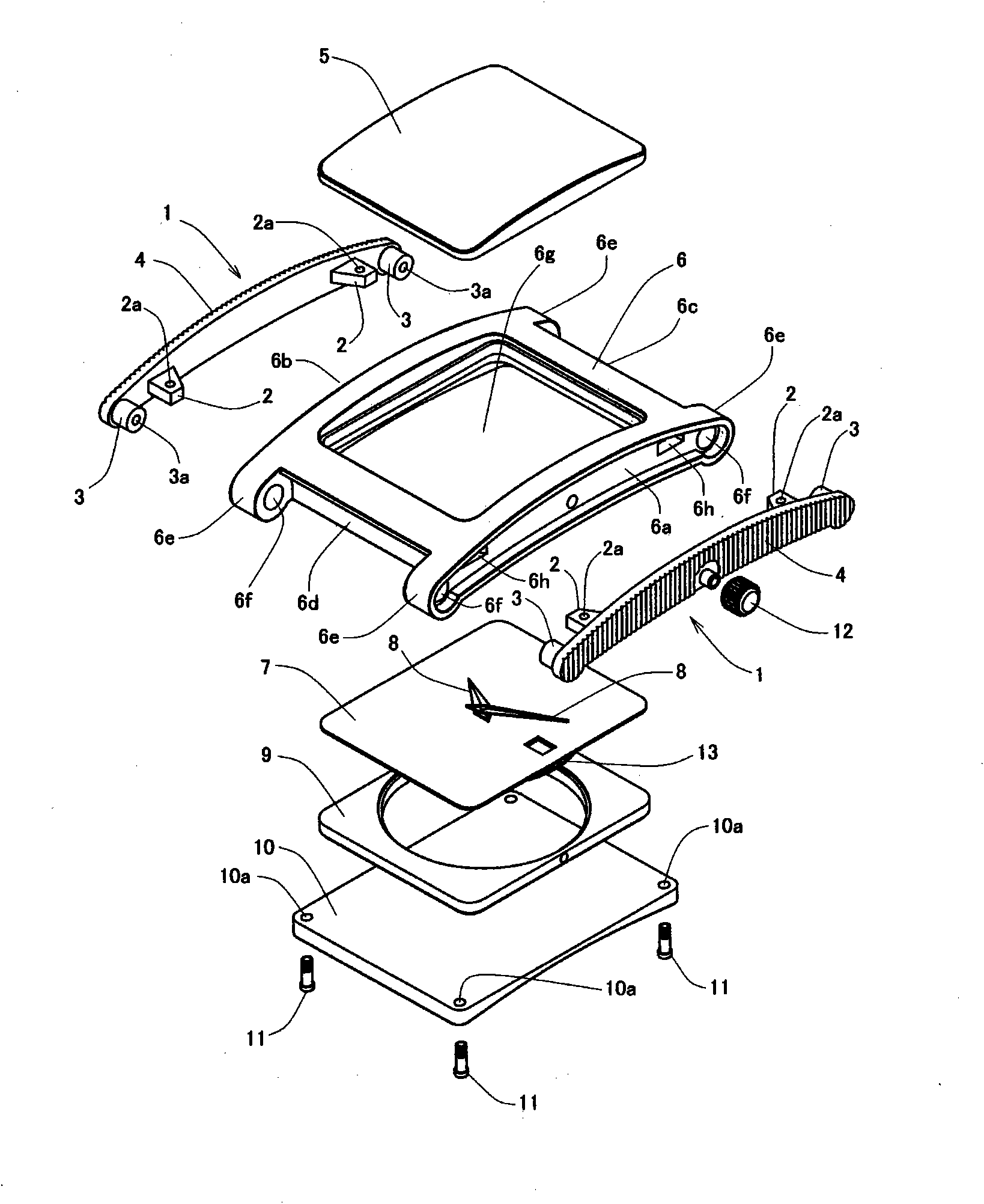
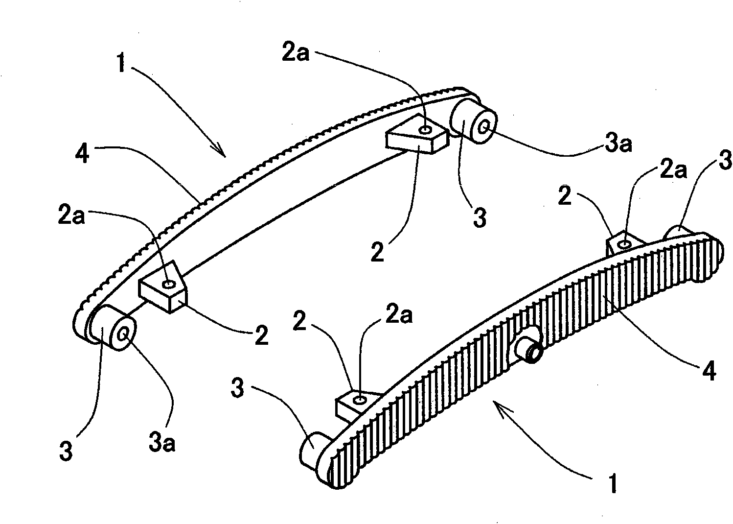
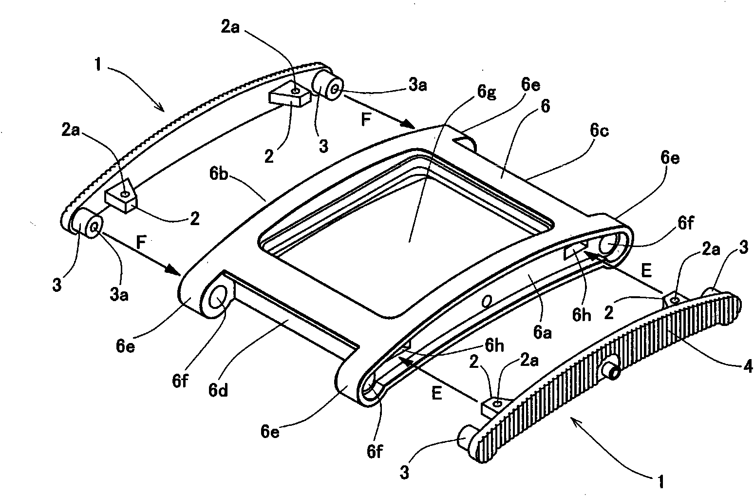
[0029] Below, refer to Figure 1 to Figure 6 An example of the watch case structure of the present invention will be described. As the best embodiment of the present invention, it is as figure 1 As shown, the housing frame main body 6 as a watch case is used as a base for component assembly, and a cover glass 5 is installed on the front side of the housing frame main body 6. In addition, the pointer 8, the dial 7, and the movement (movement) are assembled from the back side. ) 13 and the whole set of timing parts of the movement bracket 9 are loaded into the interior of the inner cavity 6g, and then the back cover is screwed together by screwing the screw 11 into the threaded hole 2a of the screw locking part 2 provided on the decoration part 1. 10 is fixed to the side of the case frame main body 6 to be assembled as a confidential watch case 100, and has a characteristic in the mounting structure of the decorative member 1 disposed on the 3 o'cl...
PUM
 Abstract
Description
Claims
Application Information