

High-pressure discharge lamp
A high-pressure discharge lamp and discharge vessel technology, which is applied to parts and components of gas discharge lamps, can solve problems such as high cost, high manufacturing cost and production cost, and achieve good ignition effect.
- Summary
- Abstract
- Description
- Claims
- Application Information
AI Technical Summary
Problems solved by technology
Method used
Image

Examples
Embodiment Construction
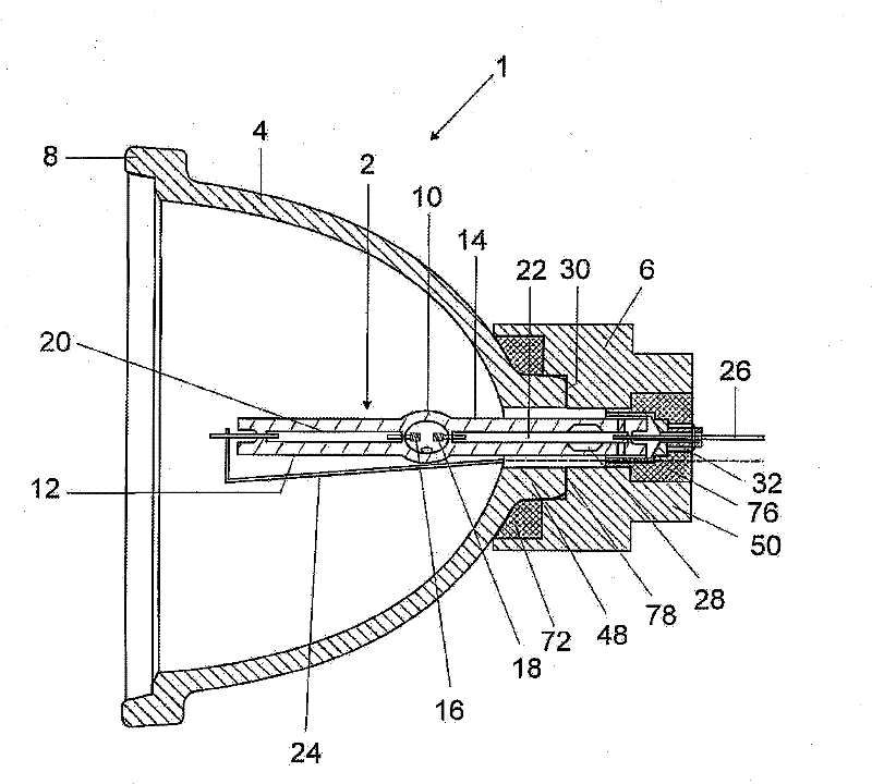
[0030] figure 1 A simplified longitudinal section through an exemplary embodiment of a high-pressure discharge lamp 1 is shown. The high-pressure discharge lamp is designed as a reflector lamp and has a burner 2 which, together with a reflector 4 , is inserted into a ceramic part 6 . The reflector 4 consists, for example, of glass and is provided with a reflective coating. A front disk or a front cover can be inserted into the front flange 8 in the direction of radiation of the lamp. The burner 2 essentially consists of an approximately centrally arranged discharge vessel 10 on which two rods 12 , 14 arranged on the axis of the reflector 4 are arranged. In the discharge vessel 10 there are two electrodes 16 , 18 spaced apart from one another and made of tungsten, for example, which are connected to each other by sealing foils 20 , 22 made of molybdenum fused into the rods 12 , 14 . The power supply lines 24, 26 are contacted. In the exemplary embodiment shown, the supply l...
PUM
 Abstract
Description
Claims
Application Information