Server device and message transmission method

A technology of message sending and server, which is applied in subscriber special service, automatic switching office, telephone communication, etc., and can solve problems such as inability to send messages and lack of freedom

Inactive Publication Date: 2010-09-01
NTT DOCOMO INC
View PDF2 Cites 3 Cited by
  • Summary
  • Abstract
  • Description
  • Claims
  • Application Information

AI Technical Summary

Problems solved by technology

Therefore, there is no degree of freedom in the timing of sending a message, and in selecting and sending a plurality of messages corresponding to a communication partner, and the user cannot perform various communication services according to the communication partner and calling, called, and talking. state to send messages flexibly

Method used


Image

  • Server device and message transmission method
  • Server device and message transmission method
  • Server device and message transmission method

Examples


Embodiment 2

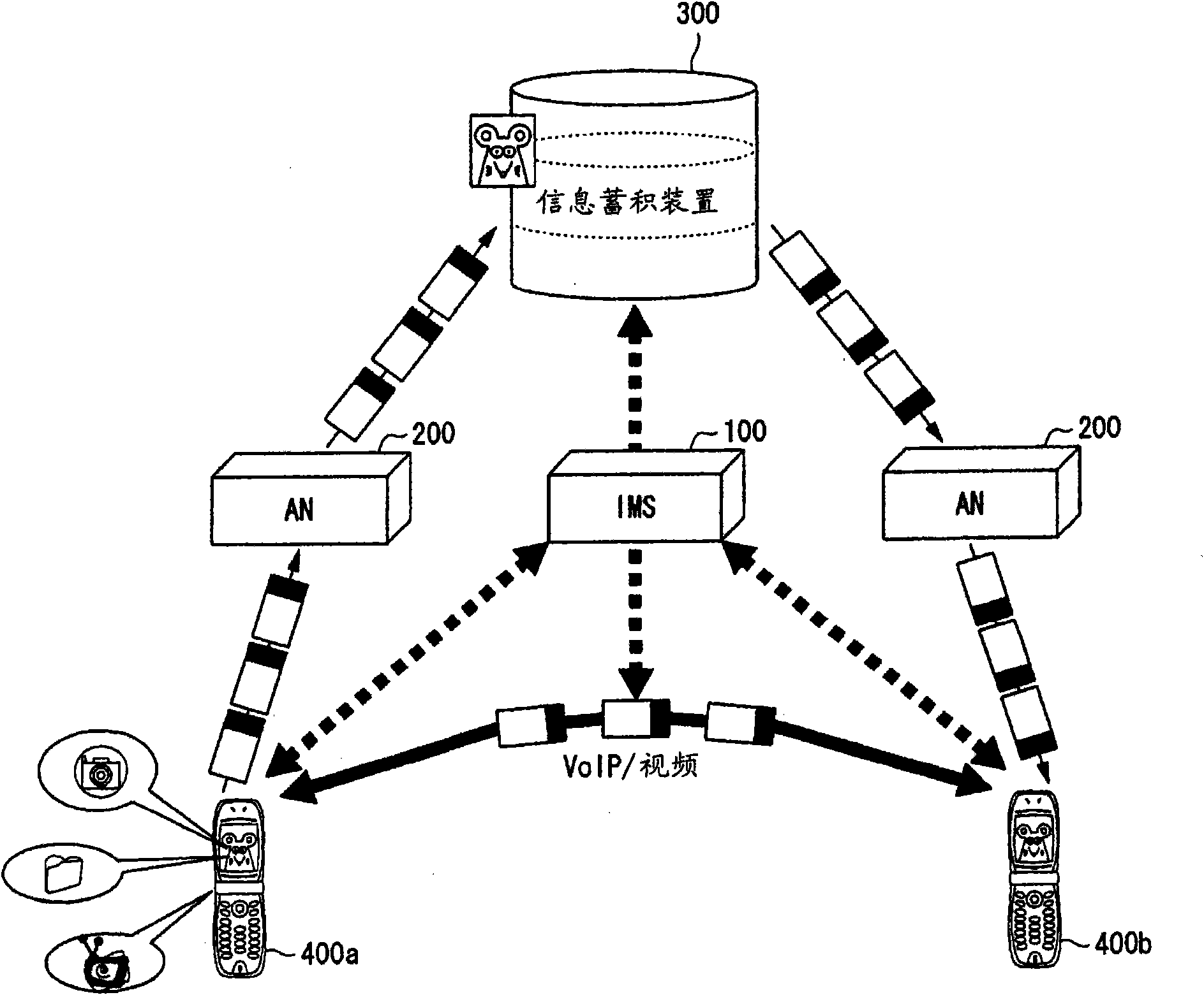
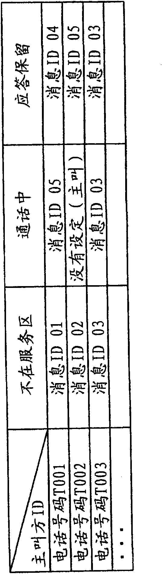
[0082] Embodiment 2 will be described below. In the first embodiment, the message to be sent is determined according to the instruction input by the called party, but in the second embodiment, the message to be sent is determined based on the pre-registered determination condition. As a premise, it is assumed that the called party has previously Figure 4 The shown table is registered in the message transmission condition storage unit 101 of the IMS 100 , and the current state of the called party "in a meeting" is registered in the presence DB.

[0083] The calling party uses the calling terminal 400a of the telephone number T001 to make a call to the called terminal 400b.

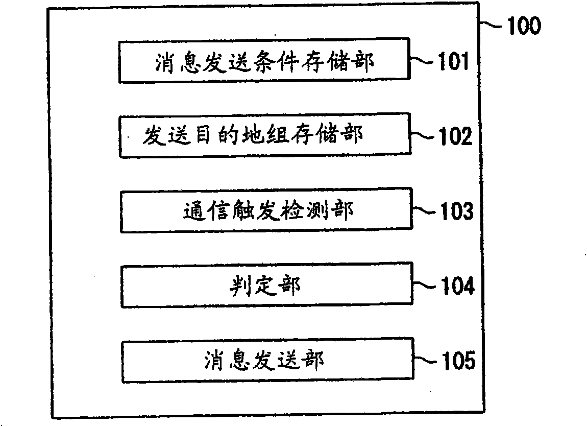
[0084] Thus, the communication trigger detection unit 103 of the IMS 100 detects the trigger point 7 "when the called MS answers" (step S101). The determination unit 104 of the IMS 100 acquires the called party's presence "in a meeting" from the presence DB. Then, according to Figure 4 In the table sh...

Embodiment 3

[0087] Embodiment 3 is an example of sending a pre-registered fixed message. The calling party registers in the information storage device 300 in advance the message that wants to convey to the other side, for example, " I am in a hurry now, please call immediately (message ID: 04) ", " I have launched the emergency contact network. The content is ○○ (message ID: 05)", "about ○○, please reply "yes" or "no" by email (message ID: 06)", etc. Then, the calling party inputs the telephone number of the called terminal 400b of the other party to the calling terminal 400a to make a calling. Next, the calling party designates the ID of the message to be sent, and inputs an instruction to send the message. Thus, the calling terminal 400a sends a message sending indication signal to the network.

[0088] When the other party responds, the communication trigger detection unit 103 of the IMS 100 detects Figure 6 Trigger point 10 shown. Also, when the other party does not respond, the ...

Embodiment 4

[0093] Below, refer to Figure 9 and Figure 10 The flow diagram shown illustrates Example 4. In Embodiment 4, a case will be described in which a fixed message registered in advance is transmitted to a plurality of objects by specifying a group number.

[0094] First, the calling party operates the calling terminal 400a, specifies a message ID and a group number, and makes a call. Thus, the calling terminal 400a sends a message sending indication signal to the communication system.

[0095] In the communication system, after the IMS 100 receives the message transmission instruction signal, the communication trigger detection unit 103 detects the trigger point ( Figure 9 in step S101). The process of detecting the trigger point is the same as that in Embodiment 3.

[0096] Next, the discrimination unit 104 discriminates the message to be transmitted based on the message ID included in the message transmission instruction signal (step S102).

[0097] In addition, the mes...


PUM


Abstract

This object to provides a server device and a message transmission method that make it possible to flexibly transmit an arbitrary message at various timing in a communication service condition. When a communication trigger detection unit (103) of an IMS (100) detects a trigger point, a judgment unit (104) judges a message to be transmitted in accordance with at least one of a kind of a communication service condition, a transmission destination of the message, presence information and an instruction input. A message transmission unit (105) instructs an information storage device (300) to transmit the judged message to be transmitted and the information storage device (300) transmits the judged message to the transmission destination.

Description

technical field [0001] The present invention relates to a server device for transmitting a message, and a method for transmitting a message. Background technique [0002] Conventionally, as an example of using the information accumulated by the user for communication, there is a response message in the answering machine service. The so-called answering machine service refers to the service that when the called terminal cannot answer the call from the calling terminal, the calling terminal is sent instead of a response message recorded in advance by the user of the called terminal (for example, refer to Japanese Patent Laid-Open 2001 - Bulletin No. 103132). [0003] However, this structure of message transmission in the answering machine service is exclusively used in the answering machine service, and is a structure that is sent only under specific timing and conditions. Therefore, there is no degree of freedom in the timing of sending a message, and in selecting and sendi...

Claims


Application Information

Patent Timeline
Patent Type & Authority Applications(China)
IPC IPC(8): H04M3/53
CPCH04M2203/2044H04M3/53366H04M15/85H04M15/835H04L29/06217H04M3/42374H04M3/42382H04M15/84H04M2203/651H04L51/14H04L65/1016H04M15/844H04M2203/654H04L51/214
Inventor 田村基薮崎正实塚田千佳子
Owner NTT DOCOMO INC
Why Eureka
Try Eureka