Shield machine

A shield machine and shell technology, which is applied in mining equipment, earth-moving drilling, tunnels, etc., can solve the problems of incapable of cambered pipes, easy wear of cutting tools, low cutting efficiency, etc. Damage, high cutting efficiency

Inactive Publication Date: 2010-09-08
唐兆连
View PDF7 Cites 16 Cited by
  • Summary
  • Abstract
  • Description
  • Claims
  • Application Information

AI Technical Summary

Problems solved by technology

The currently used shield machine includes a cylindrical shell, and a cutting device is provided at the front of the shell. The cutting device includes a circular cutter head, and several cutting knives are fixedly connected to the cutter head. The cutting knives are located at the same diameter. In the plane, during the cutting process, the cutting knife is subjected to a large force, the cutting knife is easy to wear, and the cutting efficiency is low, thereby reducing the efficiency of pipeline laying. The cutting angle of the cutting knife cannot be adjusted, and the shield machine can only perform straight-line construction. Cannot be laid with curved pipes

Method used


Image

  • Shield machine
  • Shield machine
  • Shield machine

Examples


Embodiment

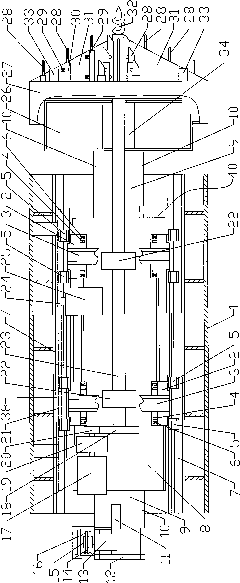
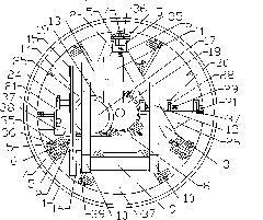
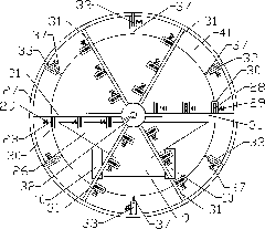
[0021] Example: as attached figure 1 And attached figure 2 As shown, the shield machine includes a cylindrical casing 1, a cutting device is provided at the front of the casing 1, and three guide rails 7 are arranged inside the casing 1, and three guide rails 7 are provided with shafts that can move along the axis of the casing 1. To the sliding seat 40 that slides back and forth, the bottom of the sliding seat 40 is fixedly connected with a conveying device, and the upper part of the sliding seat 40 is provided with a cutting power transmission device and a feeding power transmission device, and the cutting power transmission device is connected with the cutting device.

[0022] Sliding seat 40 comprises two polygonal supports, and polygonal support is triangular support 3, and two supports 3 are connected by channel steel, and the three corners of support 3 are all provided with the sliding adjusting device that cooperates with guide rail 7, and the bottom of support 3 is p...


PUM


Abstract

The invention relates to a shield machine which comprises a shell, wherein the front part of the shell is provided with a cutting device, a slide seat is arranged in the shell, the upper part of the slide seat is provided with a cutting power transmission device and a feeding power transmission device, the lower part of the slide seat is provided with a conveying device; the cutting device comprises a tool rest shell, the tool rest shell is provided with a plurality of cutter bodies, each cutter body is provided with a plurality of cutting tools, and the cutting tools are arranged in a way that the distance between the cutting edge of each cutting tool and the end surface of the tool rest shell successively decreases along the radial direction of the tool rest shell from inside to outside; and in the cutting process, the cutting tool adjacent to the center of the tool rest shell perform the cutting operation first, and then, the cutting tools away from the center of the tool rest shell successively perform the cutting operation, thereby high cutting efficiency is achieved, and the pipeline laying efficiency is improved. Besides, the cutting angle of the cutting tools can be adjusted by sliding the adjusting device, thereby the laying of the bent pipeline is realized.

Description

technical field [0001] The invention relates to a shield excavating device, in particular to a shield machine. Background technique [0002] At present, when laying underground pipelines, the trenches for laying pipelines are usually dug first, then the pipelines are laid in the trenches, and then the trenches are filled with soil. Low. In order to reduce the amount of construction and improve construction efficiency, people began to use the shield tunneling method for construction. During construction, the cutting device at the front of the shield machine is used to process the holes required for laying the pipeline, and the pipeline to be laid is pushed against the shield. At the back of the shield machine, the pipe jacking machine at the back of the pipeline pushes the pipe into the hole processed by the shield machine to complete the laying of the pipeline. The currently used shield machine includes a cylindrical shell, and a cutting device is provided at the front of ...

Claims


Application Information

Patent Timeline
Patent Type & Authority Applications(China)
IPC IPC(8): E21D9/08E21D9/093
Inventor 唐兆连
Owner 唐兆连
Why Eureka
Try Eureka