Water heater with lower inner liner pressure

A water heater and inner tank technology, applied in the field of water heaters that reduce the pressure of the inner tank, can solve problems such as affecting users' normal water use, scalding people, and users not being able to use them normally.

Active Publication Date: 2012-09-19
HAIER GRP CORP +1
1 Cites 17 Cited by

AI-Extracted Technical Summary

Problems solved by technology

Patent ZL02115118.0 is a scheme to close the water inlet valve when the pressure exceeds a certain value, but when the user is using hot water, once the inner tank pressure exceeds the set value, the connection between the inner tank and the tap water system will be cut off, causing the user to fail to operate normally. use
And when the pressure of the inner tank exceeds the standard, the solution of the patent ZL02115118.0 can only stop the continuous increase of the pressure ...

Abstract

The invention discloses a water heater with lower inner liner pressure. The water heater comprises an inner liner, a water inlet pipe, a water outlet pipe, a hydraulic valve and a cold water pipeline communicated with the water inlet pipe and the hydraulic valve; the water heater also comprises a first electromagnetic valve used to control the disconnection or connection of the water inlet pipe, a second electromagnetic valve used to control the inner liner to connect or disconnect with the atmosphere, a water flow detector used to detect the water flow in the cold water pipeline and a controller used to output control signals for controlling the disconnection or connection of the first electromagnetic valve and second electromagnetic valve according to the detection signals of the water flow detector. When hot water is not used, the electromagnetic valve on the water inlet pipe of the water heater of the invention is used to close the water inlet pipe all along, thus avoiding that the inner liner always bears the tap water pressure; and the electromagnetic valve on the water outlet pipe is used to ensure that the water outlet pipe is communicated with the atmosphere, thus avoiding the pressure on the inner liner owning to the volume expansion of water in heating process. When hot water is used, the water heater of the invention can avoid that hot water flows directly from themixing valve to scald human.

Application Domain

Fluid heaters

Technology Topic

PipingVolume expansion +8

Image

  • Water heater with lower inner liner pressure
  • Water heater with lower inner liner pressure
  • Water heater with lower inner liner pressure

Examples

  • Experimental program(1)

Example Embodiment

[0027] The present invention will be described below with reference to the accompanying drawings and various embodiments.
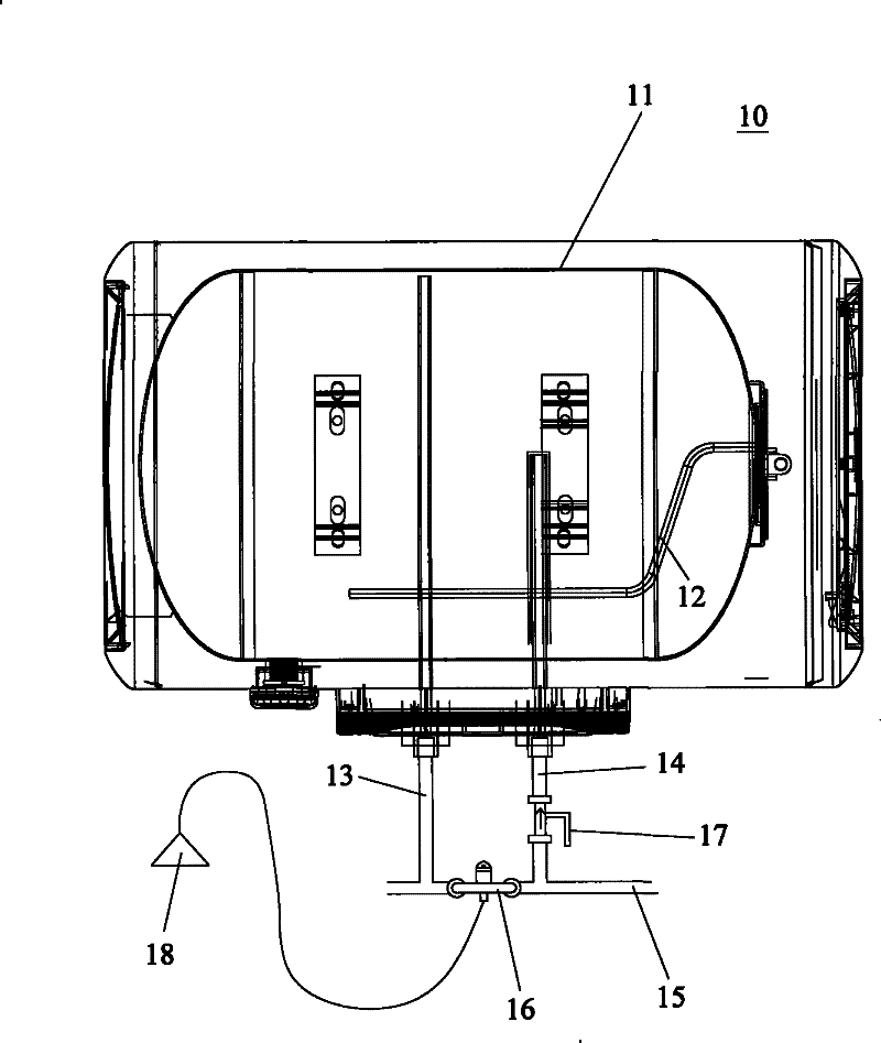
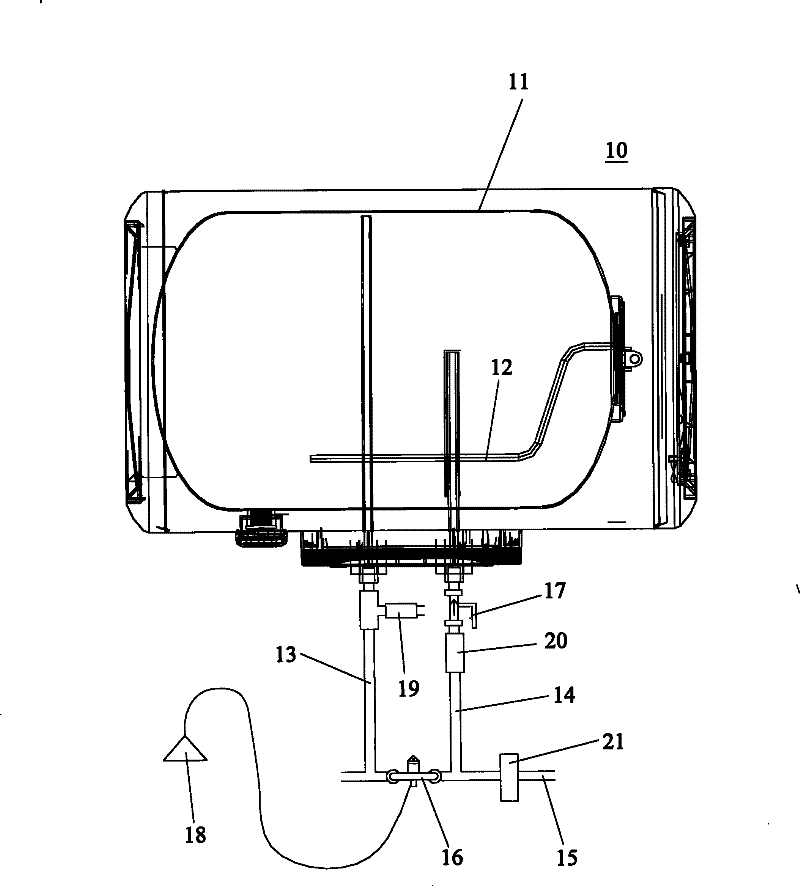
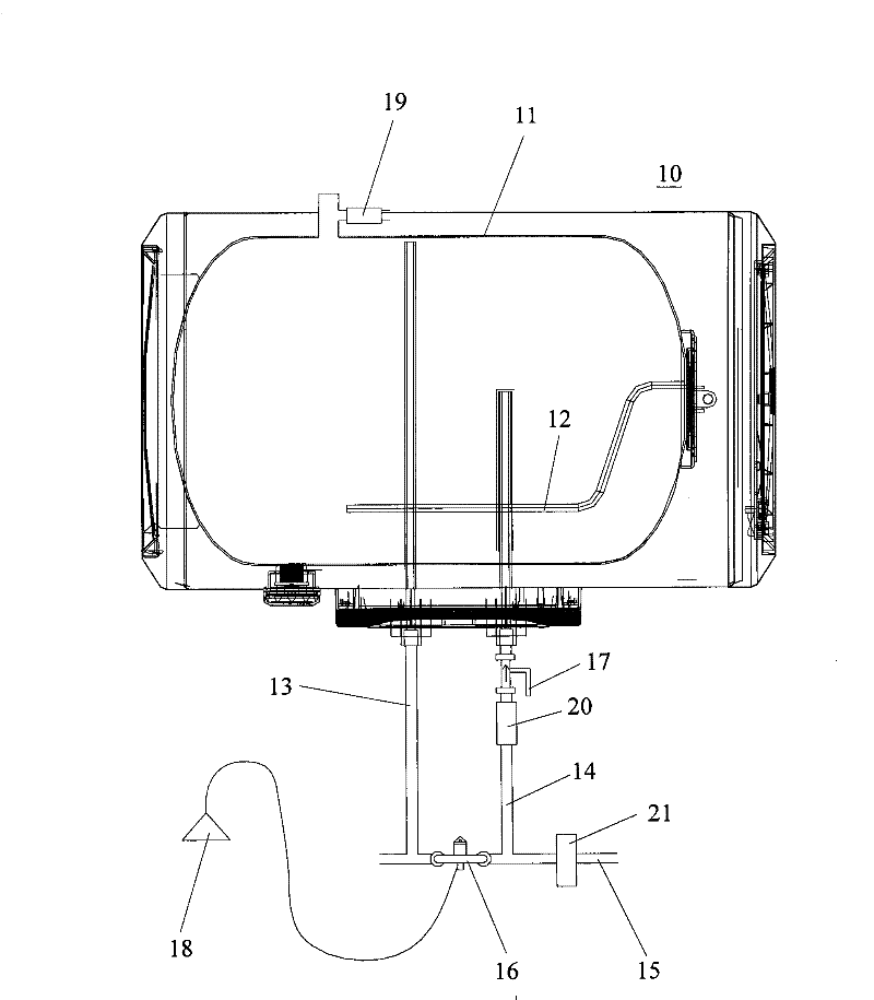
[0028] figure 2 A schematic diagram of the structure of the electric water heater according to the first embodiment of the present invention is shown, Figure 4 A schematic block diagram of the pressure control of the inner tank of the water heater according to the present invention is shown. combined reference figure 2 and Figure 4 , the water inlet pipe 14 of the electric water heater 10 is provided with a first solenoid valve (ie, a water inlet solenoid valve) 20 , and the first solenoid valve 20 is used to control the cutoff or communication of the water inlet pipe 14 . A second solenoid valve (ie, a water outlet solenoid valve) 19 is provided on the water outlet pipe 13, and the second solenoid valve 19 is used to control the communication or disconnection of the inner tank 11 with the atmosphere. A water flow detector 21 is provided on the cold water pipeline 15 leading to the water inlet pipe 14 and the water regulating valve 16 , and the water flow detector 21 is used to detect whether there is water flowing in the cold water pipeline 15 .
[0029] The cold water pipeline 15 includes a cold water pipe branch connected with the water regulating valve 16 and the water inlet pipe 14 and a cold water pipe trunk connected with the cold water pipe branch. The water flow detector 21 can be arranged on the branch of the cold water pipe connected to the water regulating valve 16, or can be arranged on the main road of the cold water pipe.
[0030] When there is water flowing in the cold water pipeline 15, a first detection signal is sent to the controller 30, and the controller 30 closes the second solenoid valve 19 and opens the first solenoid valve 20 according to the first detection signal. The tank is not connected to the atmosphere, and cold water can enter the tank from the water inlet pipe 14, and the user can normally use the electric water heater 10 for bathing; when the water flow detector 21 detects that there is no water flow in the cold water pipeline 15, it sends a message to the controller. 30 sends a second detection signal, and the controller 30 closes the first solenoid valve 20 and opens the second solenoid valve 19 according to the second pulse signal. At this time, the inner tank is connected to the atmosphere, and cold water cannot enter from the water inlet pipe 14. At this time, the liner does not withstand the water pressure from the water pipe and the pressure after the water is heated and expanded.
[0031] The above-mentioned water flow detector 21 may be a flow switch for detecting the flow rate of tap water, or a water flow switch (usually also referred to as a water-operated switch) for detecting whether there is a water flow.
[0032] image 3 A schematic structural diagram of the electric water heater according to the second embodiment of the present invention is shown. As shown in the figure, the difference between the electric water heater of this embodiment and the electric water heater of the first embodiment is that the second solenoid valve 19 for controlling the connection or disconnection of the inner pot with the atmosphere is provided on the top of the inner pot 11 .
[0033] Figure 5 A flow chart of the pressure control of the inner tank of the water heater according to the present invention is shown. Refer to the following Figure 4 and Figure 5 The control process of the inner bladder pressure will be described.
[0034] In step S10 , the water flow detector 21 detects the water flow in the cold water pipeline 15 , and sends a detection signal to the controller 30 when the water flow is detected.
[0035] In step S20, the controller 30 judges according to the received detection signal. When it is judged that there is water flow, step S31 is executed, that is, the controller 30 sends a control signal to open the solenoid valve of the water inlet and close the solenoid valve of the water outlet. At this time, the water heater enters. Use state; when it is judged that there is no water flow, step S32 is executed, that is, the controller 30 sends a control signal, closes the water inlet solenoid valve, and opens the water outlet solenoid valve, so that the liner communicates with the atmosphere. In this way, the pressure of the inner bladder is reduced compared to the pressure of the inner bladder after being heated and expanded by tap water and water.
[0036] After this process is completed, the water flow detector detects the water flow again, and repeats this process.
[0037] The water flow in the cold water pipeline 15 is controlled by the water regulating valve. When the water regulating valve is opened to mix the cold water and the hot water, there will be water flow in the cold water pipeline 15 due to the pressure of the tap water, which is detected by the water flow detector. When the water regulating valve is opened to the position where hot water is directly discharged, since there is no water flow in the cold water pipeline 15, the solenoid valve 20 on the water inlet pipe 14 will not be opened, so the hot water in the inner tank 11 will not flow out directly. In this way, the accident of scalding people caused by direct hot water can be avoided.
[0038] It can be seen from the above description that when the electric water heater of the present invention is not using hot water, the electromagnetic valve on the water inlet pipe always closes the water inlet pipe, and the electromagnetic valve on the water outlet pipe is always open to keep the water outlet pipe and the atmosphere connected, so that the inner The bladder is in a pressure-free state, extending the service life of the inner bladder. At the beginning of use, it can avoid the accident of scalding people caused by direct hot water from the mixing valve.
[0039]Those skilled in the art can easily understand that the water heater of the present invention that prevents the inner tank from being always under pressure can be applied not only to electric water heaters, but also to heat pump water heaters, so as to avoid the inner tank or water tank used for water storage from always under pressure state, so as to prolong the service life of the inner tank, and at the same time avoid the accident of scalding people caused by direct hot water from the mixing valve.
[0040] The above descriptions are only preferred embodiments of the present invention, and are not intended to limit the present invention. For those skilled in the art, the present invention may have various modifications and changes. Any modification, equivalent replacement, improvement, etc. made within the spirit and principle of the present invention shall be included within the protection scope of the present invention.

PUM

no PUM

Description & Claims & Application Information

We can also present the details of the Description, Claims and Application information to help users get a comprehensive understanding of the technical details of the patent, such as background art, summary of invention, brief description of drawings, description of embodiments, and other original content. On the other hand, users can also determine the specific scope of protection of the technology through the list of claims; as well as understand the changes in the life cycle of the technology with the presentation of the patent timeline. Login to view more.
Why Eureka
Try Eureka