Drive hub bearing unit assembly clearance measurement method

A technology of wheel hub bearing and measurement method, which is applied to measurement devices, instruments, electric devices, etc., can solve the problems of insufficient rotation of the main shaft, increased errors, poor repeatability, etc., to eliminate interference errors, improve detection efficiency, and measure Data-reliable effects

Active Publication Date: 2010-09-08
HUBEI NEW TORCH SCIENCE & TECHNOLOGY CO LTD
View PDF0 Cites 15 Cited by
  • Summary
  • Abstract
  • Description
  • Claims
  • Application Information

AI Technical Summary

Problems solved by technology

[0002] At present, the method of measuring the bearing clearance in the bearing industry is generally: use the outer ring tightening device, the upper and lower load loading device of the inner ring, and the detection instrument to measure or detect the bearing clearance, but in production, this method does not affect the bearing clearance. Clearance measurement is very inaccurate, especially it is difficult to accurately measure the clearance of the hub bearing unit assembly with small clearance. The existing measurement has the following shortcomings: First, in order to ensure that the loading surface of the lower pressure table is In the initial loading condition, it is in complete contact with the lower surface of the inner flange of the tested wheel hub bearing unit assembly. Generally, a ball head self-aligning device is used. Although such a device can ensure relatively complete contact, the wheel hub bearing unit assembly There will be a large parallel difference between the lower surface of the outer flange positioning device and the upper surface of the loading device, and it is very random, so that under the condition of lower load, the inner flange of the hub bearing unit assembly There will be a certain amount of deviation between the center of the raceway and the center of the raceway of the outer flange of the hub bearing unit assembly, and the inner flange of the hub bearing unit assembly will make two static limits under the action of the lower pressure table When the position is displaced, if the measuring head does not fall on the center of the inner flange very accurately, the measured displacement at this time becomes very random due to the random deviation of the inner flange of the hub bearing unit assembly. The accuracy cannot be guaranteed; another big defect is that the inner flange of the hub bearing unit assembly is under the action of the upper and lower loads, and the most ideal state to be achieved is that the raceways of the inner flange of the hub bearing unit assembly are opposite to each other. The upper and lower limit positions of the outer flange raceway of the hub bearing unit assembly can ensure the accurate measurement of the clearance, but due to the interference error between the inner and outer raceways of the hub bearing unit assembly and the cage, it is not possible to make all The rolling element is in full contact with the raceway, so that the ideal limit position cannot be reached. Although the existing method adds a manual device, this method can only be said to be able to reach the ideal limit position, but it cannot eliminate the influence of interference errors.
[0003] Third, the existing clearance measurement uses single-point measurement, and the repeatability cannot be guaranteed. Generally, in order to verify whether the clearance is in an accurate state, it is necessary to perform multiple manual loading measurements, which is very laborious and has poor repeatability; The display of the gap measurement is generally displayed by a torsion spring meter, and the difference needs to be calculated manually, which inevitably increases the error
[0004] Fourth, although part of the existing measurement is added to the computer software measurement, there are errors because the spindle rotation is not in place or the number of times is not enough, and the signal acquisition is not timely enough during the rotation

Method used


Image

  • Drive hub bearing unit assembly clearance measurement method
  • Drive hub bearing unit assembly clearance measurement method

Examples


Embodiment Construction

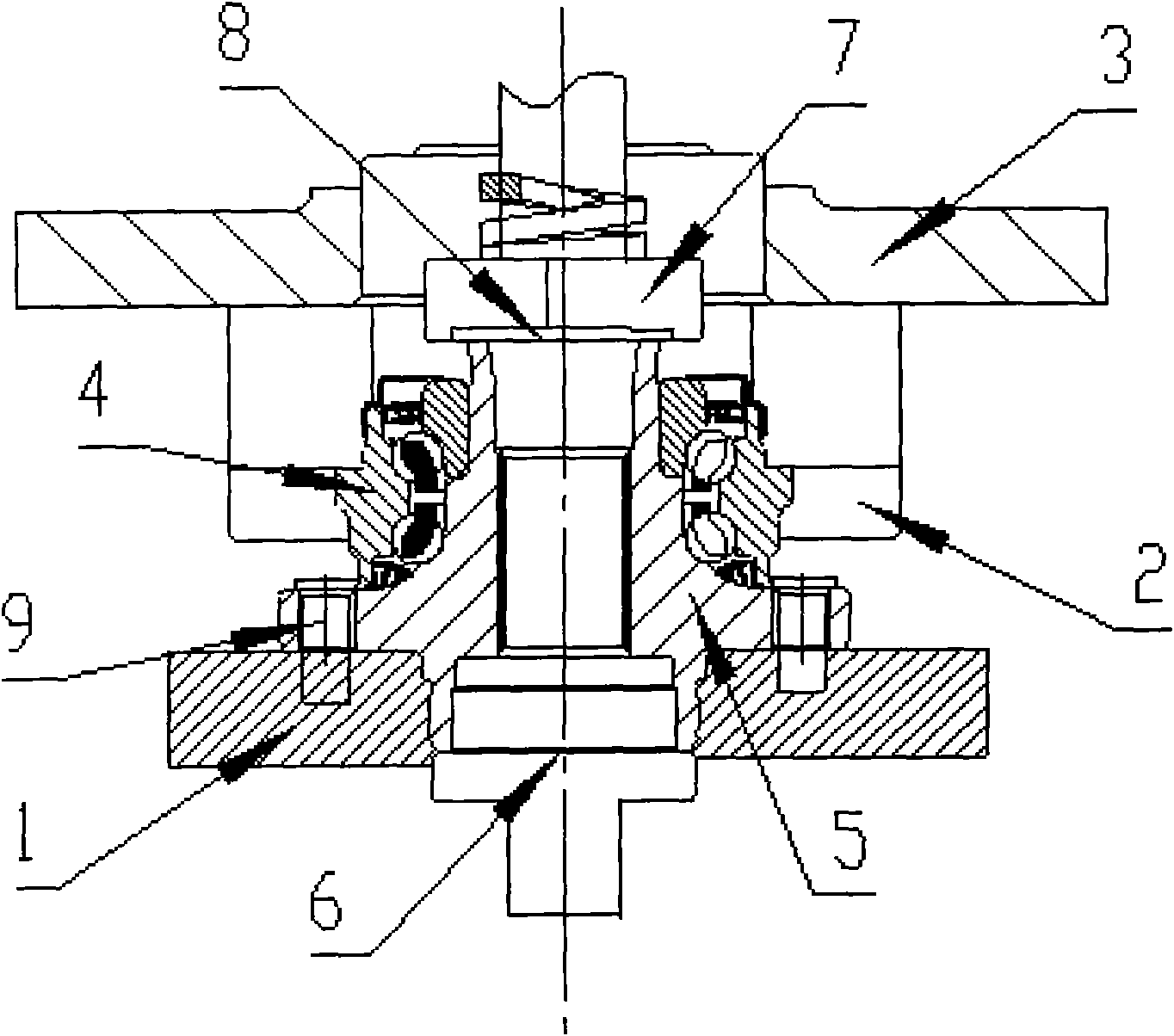
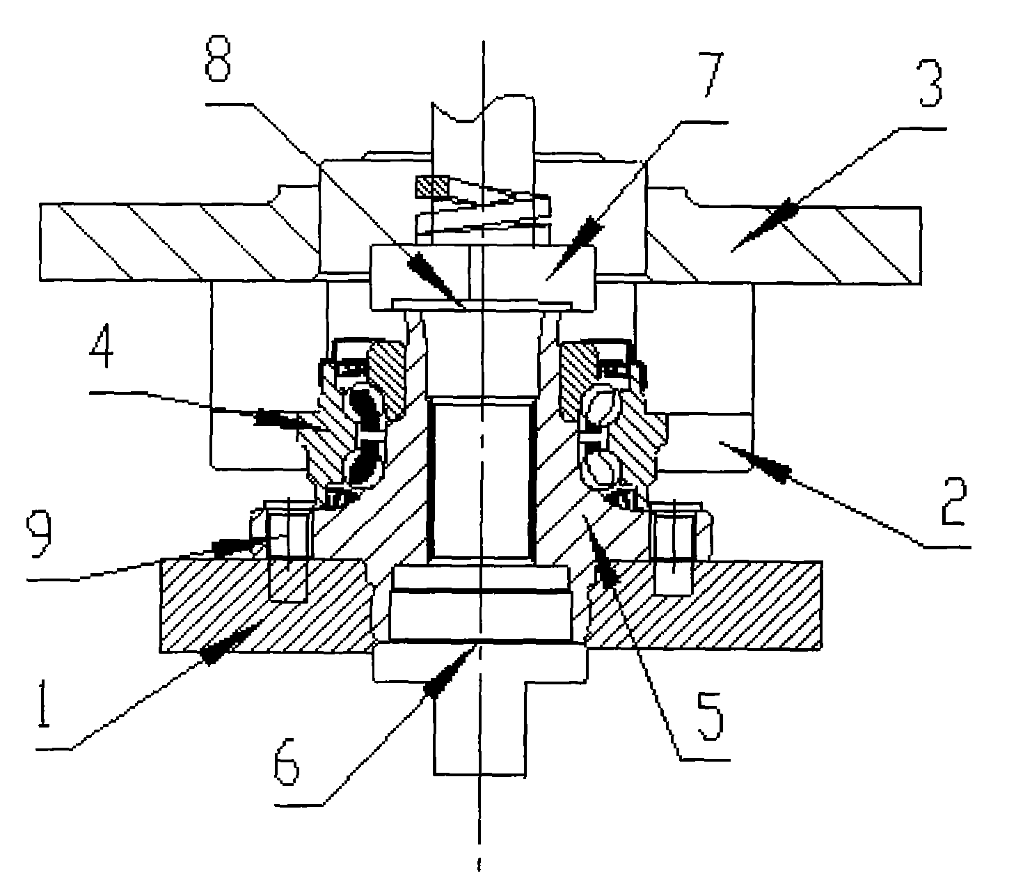
[0011] Measurement or detection method steps of the present invention are:

[0012] 1. First put the hub bearing unit assembly on the lower floating base 1, the base is provided with bolt holes, insert the bolts on the hub bearing unit assembly into the bolt holes of the base, so that the hub bearing unit assembly is fixed on the lower floating base 1;

[0013] 2. Start the hydraulic cylinder, and the hydraulic cylinder drives the clamping device 2 to move from both sides to tighten the outer flange 4 of the hub bearing unit assembly, so that the clamping device is stuck behind the lower end surface of the outer flange of the hub bearing unit assembly , start the tightening device again, and lift the outer flange of the hub bearing unit assembly longitudinally (upward);

[0014] 3. Start the servo motor 6, the servo motor 6 drives the main shaft to rotate, the main shaft drives the lower floating base 1 and the inner flange 5 of the hub bearing unit assembly to rotate, the rot...


PUM


Abstract

The invention discloses a new measurement method for automobile drive hub bearing unit assembly clearance, which can carry out rotary multiple precise measurement to the automobile drive hub bearing unit assembly clearance to reach the upper extreme position and the lower extreme position of the inner ring flange raceway relative to the outer flange raceway of the drive hub bearing unit assembly and eliminate the interference error between the outer raceway and a retainer, so all rolling elements are fully contacted with the raceways, and the repeatability precision of the clearance of the automobile drive hub bearing unit assembly is assured.

Description

technical field [0001] The invention relates to a method for measuring the clearance of a bearing unit assembly, in particular to an accurate measurement method for the clearance of an automobile drive hub bearing unit assembly. Background technique [0002] At present, the method of measuring the bearing clearance in the bearing industry is generally: use the outer ring tightening device, the upper and lower load loading device of the inner ring, and the detection instrument to measure or detect the bearing clearance, but in production, this method does not affect the bearing clearance. Clearance measurement is very inaccurate, especially it is difficult to accurately measure the clearance of the hub bearing unit assembly with small clearance. The existing measurement has the following shortcomings: First, in order to ensure that the loading surface of the lower pressure table is In the initial loading condition, it is in complete contact with the lower surface of the inner...

Claims


Application Information

Patent Timeline
Patent Type & Authority Applications(China)
IPC IPC(8): G01B7/14
Inventor 吴少伟黄朝斌王友昌张欣欣马俊
Owner HUBEI NEW TORCH SCIENCE & TECHNOLOGY CO LTD
Why Eureka
Try Eureka