Check patentability & draft patents in minutes with Patsnap Eureka AI!

Remote concentricity measuring device

A measuring device and technology of concentricity, applied in the field of measurement, can solve problems such as manufacturing difficulties, nuclear accidents, increase manufacturing difficulty, etc., and achieve the effect of improving accuracy

Active Publication Date: 2011-08-17
SHANGHAI ELECTRIC NUCLEAR POWER EQUIP CO LTD
View PDF0 Cites 2 Cited by
  • Summary
  • Abstract
  • Description
  • Claims
  • Application Information

AI Technical Summary

Problems solved by technology

The deviation of concentricity will directly affect whether the nearly ten thousand rectangular tube holes can pass through the U-shaped tube bundle with a length of more than ten meters smoothly and accurately, and in the future operation of the nuclear island, if the U-shaped tube bundle and If the tube holes are not concentric, the stress generated by them can easily lead to a nuclear accident
[0003] The traditional concentricity measurement device realizes the transmission of displacement by using a displacement transmission rod inside the device; however, due to the thin and long structure of the displacement transmission rod, it is difficult to manufacture, so the distance between the measurement hole and the reference hole requires More stringent, once the hole distance is too long, the length of the displacement transmission rod will also increase accordingly, which not only increases its manufacturing difficulty, but also, once the displacement transmission rod is deformed due to excessive length, the measurement accuracy will be greatly reduced

Method used


Image

  • Remote concentricity measuring device
  • Remote concentricity measuring device
  • Remote concentricity measuring device

Examples


Embodiment Construction

[0017] The present invention will be further described below in conjunction with drawings and embodiments.

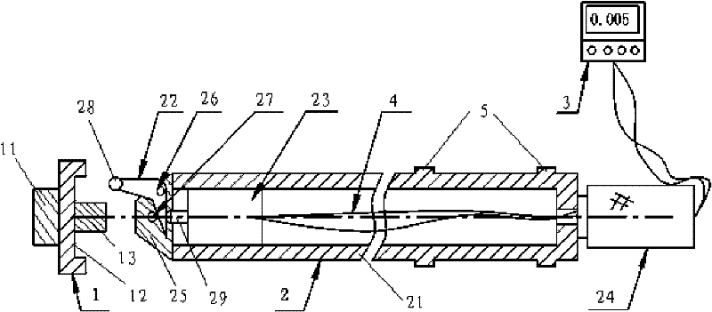
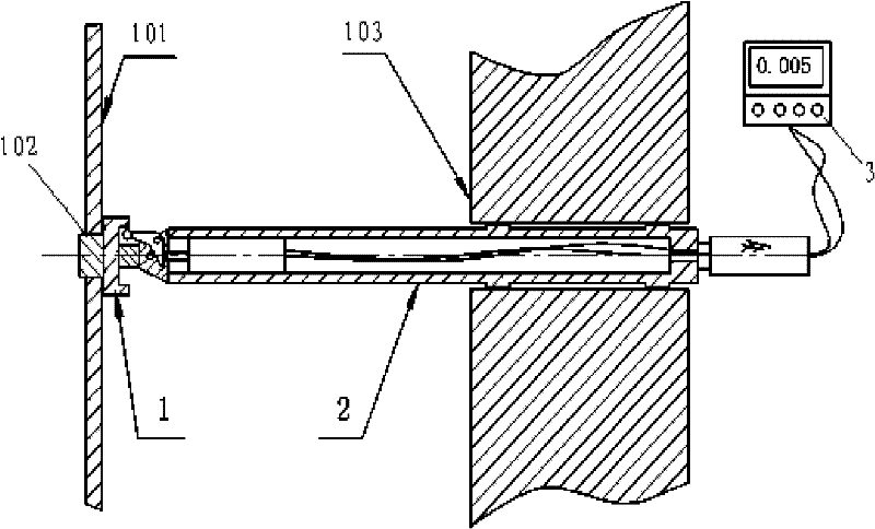
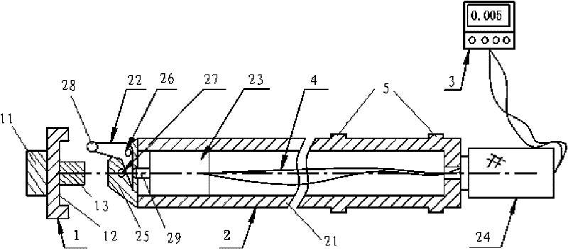
[0018] see figure 1 , figure 2 , the long-distance concentricity measuring device of the present invention is used for measuring whether the center of circle of the measured hole 102 on the support plate 101 is on the same axis as the center of the reference deep hole 103 on the nuclear power evaporator tube plate, and the measuring device includes a ring gauge 1, a measuring rod 2 and a digital display instrument 3, wherein,

[0019] One end surface of the ring gauge 1 is provided with a cylinder 11 for embedding the measured hole 102, and the other end surface is provided with a ring groove 12, the center of the ring groove 12 and the center of the cylinder 11 are located on the same axis; and A boss 13 is provided on the inner side of the ring groove 12, which is used to support the measuring rod and play a position-limiting role;

[0020] The measuring rod 2 com...


PUM


Abstract

The invention relates to a remote concentricity measuring device which is used for measuring whether a circle center of a measured hole and a center of a reference deep hole are arranged on the same axis or not. The measuring device comprises a ring gauge, a measuring rod and a digital display instrument, wherein a cylinder for being embedded into the measured hole is arranged on one end surface of the ring gauge, the other end surface is provided with an annular groove, and the inner side of the annular groove is provided with a boss; and the measuring rod comprises a pipe body which extendsinto the reference deep hole, a bending rod, a displacement sensor which is arranged at an inner cavity of the pipe and a handle which is arranged at one end of the pipe body. The invention can be used for conveniently and efficiently measuring concentricity between holes in overlong distance, thereby effectively preventing a deviation phenomenon of the concentricity between the two holes and ensuring the quality of a nuclear power evaporator product.

Description

technical field [0001] The invention relates to the technical field of measurement, in particular to a long-distance concentricity measuring device. Background technique [0002] At present, the common nuclear power evaporator tube plate has a diameter of φ3000mm and a thickness of 600mm. There are nearly 10,000 deep holes on it, and the distance from the support plate with the same diameter is 700mm. During installation, the tube plate hole should be used as a reference to measure the support. Whether the center of the circle between the corresponding holes on the board is on the same axis as the center of the reference hole, that is, to measure the concentricity between the holes. The deviation of concentricity will directly affect whether the nearly ten thousand rectangular tube holes can smoothly and accurately pass through the U-shaped tube bundle with a length of more than ten meters, and in the future operation of the nuclear island, if the U-shaped tube bundle and I...

Claims


Application Information

Patent Timeline
Patent Type & Authority Patents(China)
IPC IPC(8): G01B21/24
Inventor 江燕云刘来魁谈文龙陈意伟
Owner SHANGHAI ELECTRIC NUCLEAR POWER EQUIP CO LTD
Features
  • R&D
  • Intellectual Property
  • Life Sciences
  • Materials
  • Tech Scout
  • Unparalleled Data Quality
  • Higher Quality Content
  • 60% Fewer Hallucinations
Learn More