Exposure device and image forming apparatus

An exposure device and optical imaging technology, applied in optics, optical components, instruments, etc., can solve the problems of deviation in scanning direction, beam influence, manufacturing difficulties, etc., and achieve the effect of increasing the freedom of configuration and small exposure device

Inactive Publication Date: 2010-09-08
RICOH KK
View PDF6 Cites 8 Cited by
  • Summary
  • Abstract
  • Description
  • Claims
  • Application Information

AI Technical Summary

Problems solved by technology

[0010] In addition, in the device described in Patent Document 3, due to an increase in component accuracy or temperature, the optical path of the beam deviates along the sub-scanning direction, and the beam passing through the vicinity of the first lens may be affected by the first lens.
Also, as a method for realizing the miniaturization of the main body, for example, the interval between a plurality of arrayed parts to be scanned can

Method used


Image

  • Exposure device and image forming apparatus
  • Exposure device and image forming apparatus
  • Exposure device and image forming apparatus

Examples


Embodiment

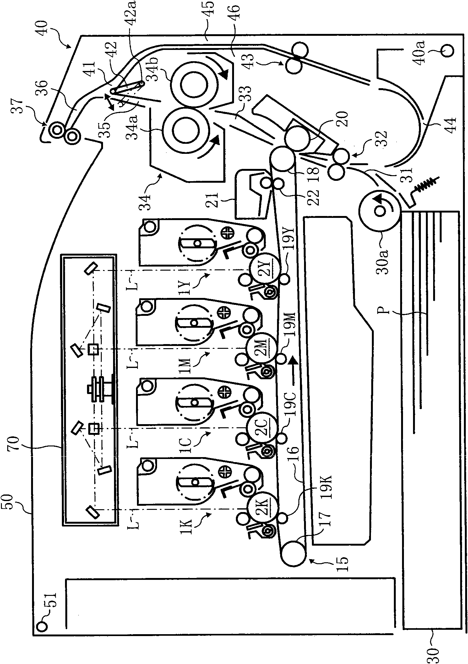
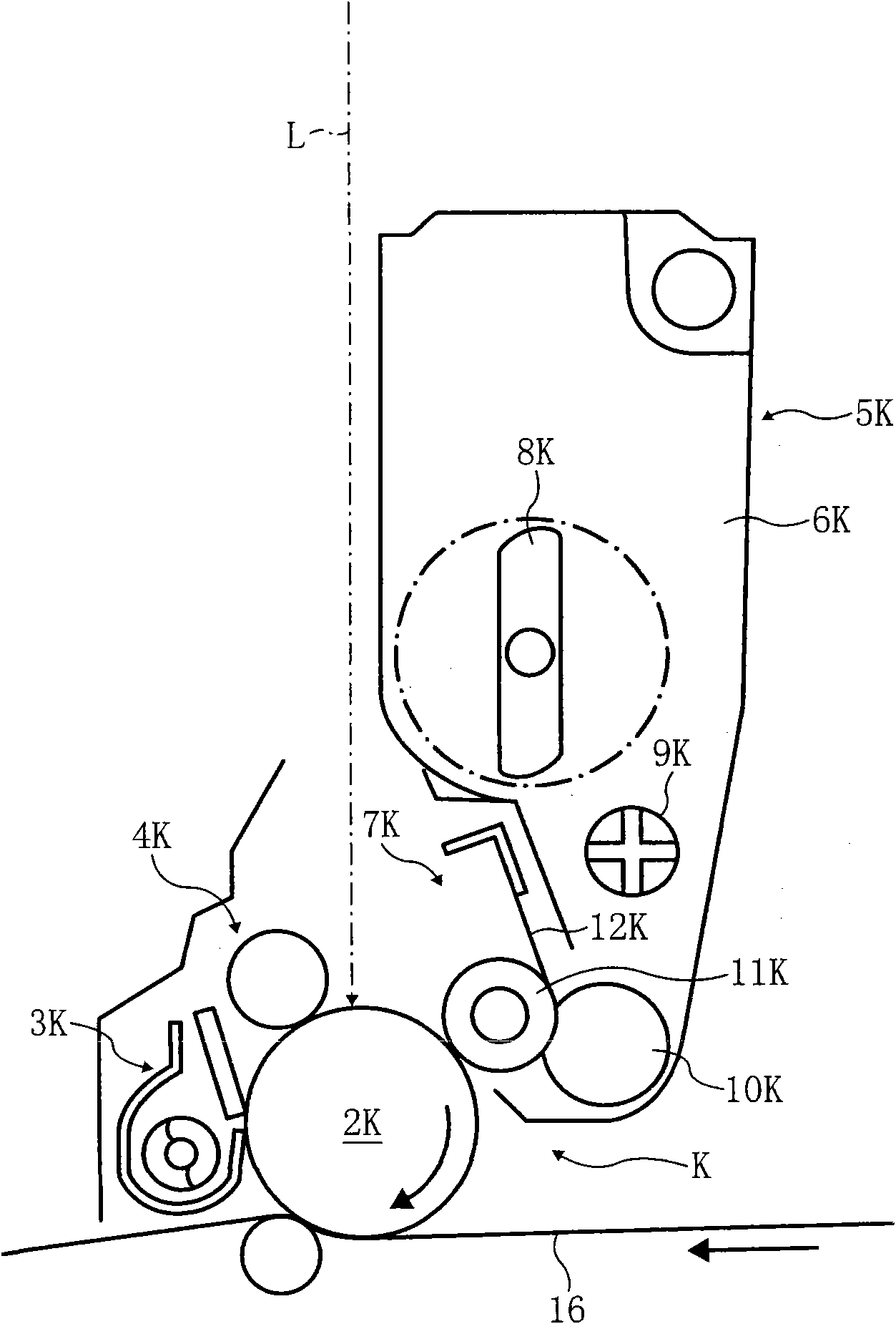
[0053] Image forming apparatuses according to the following examples will be described. Next, an electrophotographic printer (hereinafter abbreviated as "printer") will be described as an image forming apparatus according to an embodiment of the present invention. first refer to figure 1 and figure 2 to explain the basic configuration of this printer. figure 1 is a schematic configuration diagram showing a printer according to an embodiment of the present invention, figure 2 yes means figure 1 An enlarged configuration diagram of the processing unit for K of the printer shown. figure 1 The system shows the printer from the side, the right side of the figure is the front of the printer, and the left side is the rear of the printer.

[0054] This printer includes four process units 1Y, 1M, 1C, and 1K for forming toner images of yellow, magenta, cyan, and black (hereinafter abbreviated as “Y, M, C, and K”). It uses Y, M, C, and K toners of different colors as image formin...


PUM


Abstract

The invention relates to an exposure device and an image forming apparatus, the exposure device comprises a polygon mirror (71), reflective mirrors (74, 75) and a first lens (72a). The polygon mirror (71) enables a plurality of light beams (L1, L2, L3, L4) sent by a plurality of light sources to perform the deflecting scan facing to two directions opposite to a plane relatively containing a spinning axis, the reflective mirrors (74, 75) are arranged between the polygon mirror (71) and photoconductors (2Y, 2M, 2C, 2K) to guide the deflected light beams toward the photoconductors (2Y, 2M, 2C, 2K), the first lens (72a) is arranged on each light path and has f theta characteristic to concentrate the light beams (L1, L2, L3, L4) onto the photoconductors (2Y, 2M, 2C, 2K). The first lens (72a) has four optical surfaces A, B, C, D on a sub-scanning cross section, two light beams pass through the optical surface. The exposure device can not be influenced by an incident mode of a reflecting plane on which the light beams deflect toward a light deflecting device, and the freedom degrees of the scanning lens and the return parts configuring can be improved, and the invention is corresponding to the body miniaturization.

Description

technical field [0001] The present invention relates to an exposure device and an image forming device, in particular to an exposure device that deflects and scans a light beam from a light source to focus on an exposure surface, and an image forming device provided with the exposure device. Background technique [0002] A well-known optical scanning device associated with an electrophotographic image forming device such as a digital copier or a laser printer is generally configured to deflect a light beam emitted from a light source device by an optical deflector, and to scan and form an optical system such as an fθ lens and reflective light. The mirror condenses light toward the surface to be scanned to form a light spot on the surface to be scanned, and the light spot is used to perform optical scanning (main scanning) of the surface to be scanned. [0003] Here, when the optical scanning device is used as an exposure device, the photosensitive surface of a photosensitive...

Claims


Application Information

Patent Timeline
IPC IPC(8): G02B26/12
Inventor 中村贤二
Owner RICOH KK
Why Eureka
Try Eureka