

Elevator device
A technology for elevators and monitoring devices, applied in transportation, packaging, elevators, etc., can solve problems such as broken ropes, inability to detect slow rope slippage, shortened rope life, etc.
- Summary
- Abstract
- Description
- Claims
- Application Information
AI Technical Summary
Problems solved by technology
Method used
Image

Examples
Embodiment approach 1
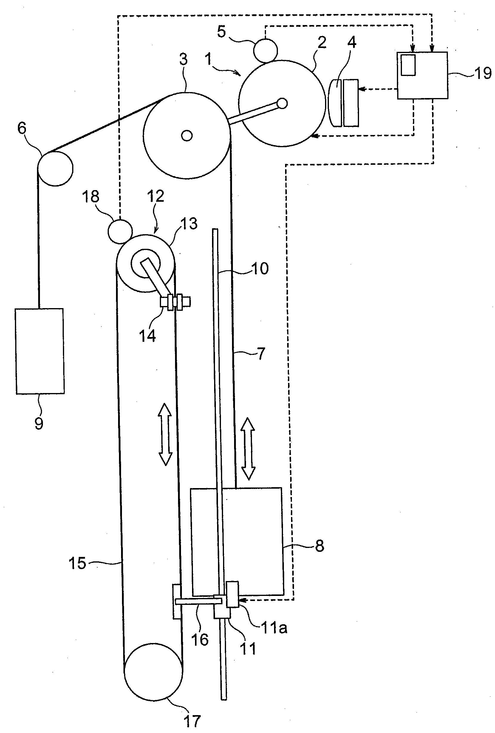
[0018] figure 1 It is a block diagram showing the elevator apparatus according to Embodiment 1 of the present invention. In the drawing, a hoisting machine 1 is provided above the hoistway. The traction machine 1 has a motor 2 , a traction sheave 3 rotated by the motor 2 , and a traction machine brake 4 that brakes the rotation of the traction sheave 3 . In this example, the traction sheave 3 is directly connected to the rotating shaft of the electric motor 2 and rotates together with the rotor of the electric motor 2 . During normal operation, the traction machine brake 4 maintains their stopped state (stationary hold) when the rotation of the motor 2 and the traction sheave 3 stops.
[0019] The hoisting machine 1 is provided with a first speed detector 5 that generates a signal corresponding to the rotational speed of the hoisting machine 1 , that is, the rotational speed of the traction sheave 3 . For the first speed detector 5, for example, an encoder (a traction machi...
Embodiment approach 2
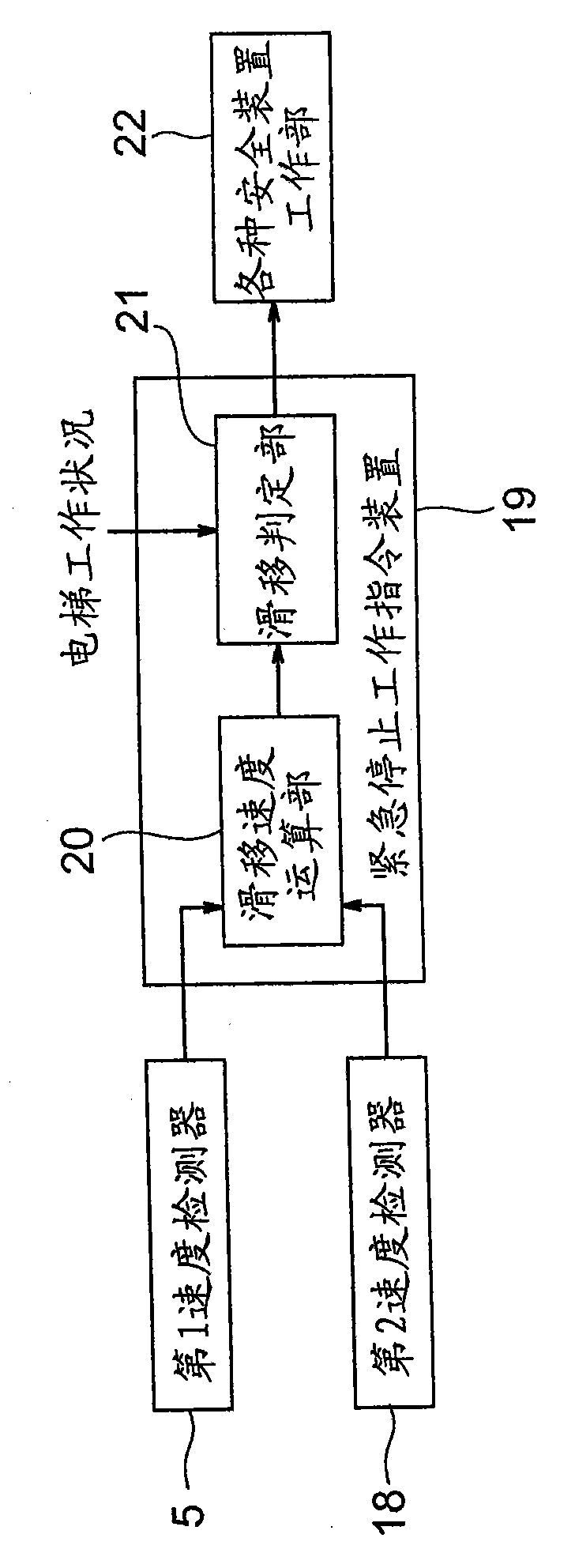
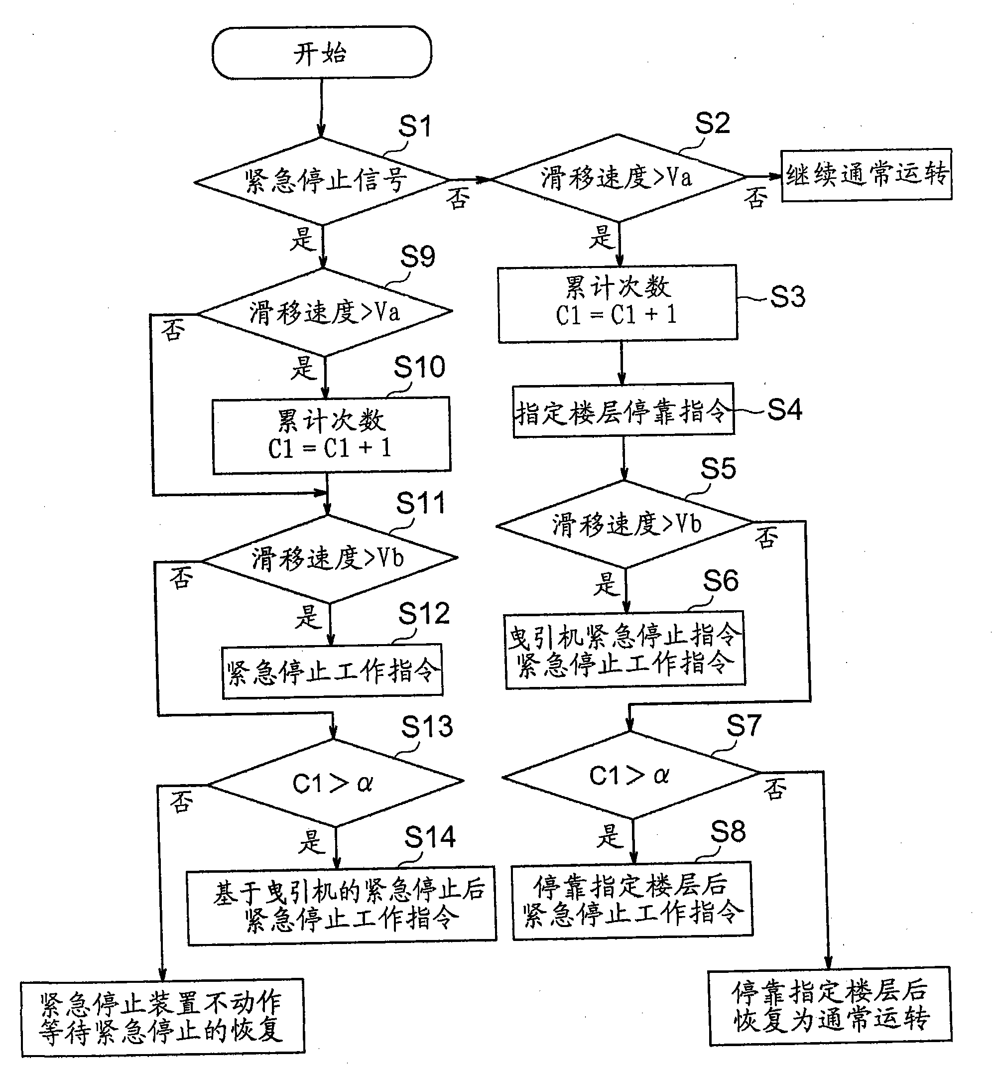
[0045] under, Figure 4 It is a block diagram showing main parts of an elevator apparatus according to Embodiment 2 of the present invention. In Embodiment 2, the emergency stop operation command device 19 calculates the slip distance of the suspension body 7 relative to the traction sheave 3 as a slip degree value. And, when the slip distance of the suspension body 7 exceeds the first distance threshold (first threshold), the emergency stop operation instruction device 19 stops the car 8 at a predetermined floor through the traction machine 1 . Also, when the slip distance of the suspension body 7 exceeds a second distance threshold (second threshold) greater than the first distance threshold, the emergency stop operation command device 19 outputs an actuation signal to the emergency stop drive unit 11a.
[0046] In addition, the emergency stop operation command device 19 has a slippage distance calculation unit 23 and a slippage determination unit 21 . The slippage distanc...
Embodiment approach 3
[0064] under, Figure 6 It is a block diagram showing main parts of an elevator apparatus according to Embodiment 3 of the present invention. In Embodiment 3, the emergency stop operation command device 19 calculates the slip distance and slip speed of the suspension body 7 relative to the traction sheave 3 as the slip degree value. And, when the slip distance of the suspension body 7 exceeds the distance threshold (first threshold), the emergency stop operation instruction device 19 stops the car 8 at a predetermined floor via the traction machine 1 . Moreover, when the slippage speed of the suspension body 7 exceeds a speed threshold value (2nd threshold value), the emergency stop operation command device 19 outputs an operation signal to the emergency stop drive part 11a.
[0065] Here, the speed threshold is set to correspond to a degree of slippage greater than the distance threshold. That is, the speed threshold is set to be larger than the numerical value obtained by ...
PUM
 Abstract
Description
Claims
Application Information