Neutron ray rotary irradiation device

A technology of rotating irradiation and neutrons, which is applied in the direction of X-ray/γ-ray/particle irradiation therapy, etc., and can solve the problems that miniaturization cannot be realized

Inactive Publication Date: 2010-09-15
SUMITOMO HEAVY IND LTD
View PDF1 Cites 22 Cited by
  • Summary
  • Abstract
  • Description
  • Claims
  • Application Information

AI Technical Summary

Problems solved by technology

However, if the same structure is used for the rotating neutron beam irradiation device in BNCT therapy, the overall size of the device will inevitably increase, and there is a problem that miniaturization cannot be achieved.

Method used


Image

  • Neutron ray rotary irradiation device
  • Neutron ray rotary irradiation device
  • Neutron ray rotary irradiation device

Examples


no. 1 Embodiment approach

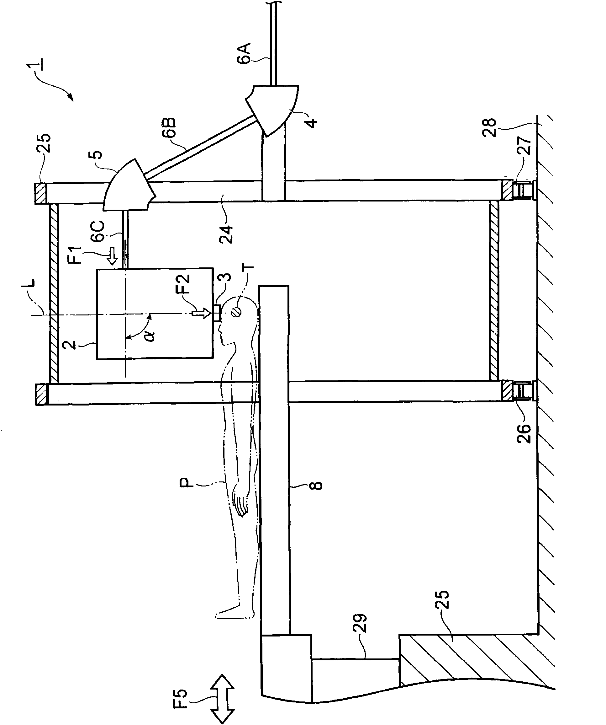
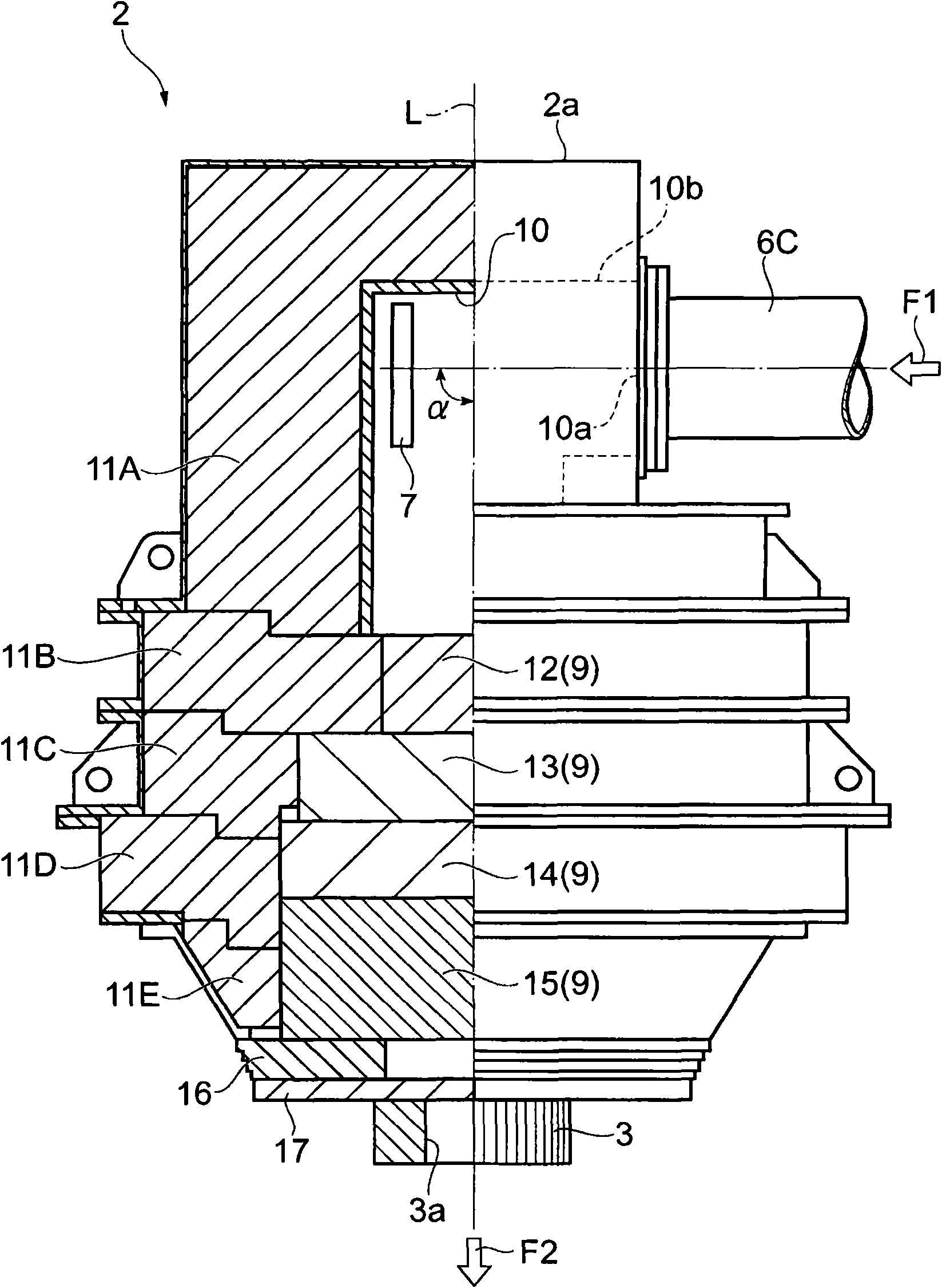
[0025] Such as figure 1 As shown, the neutron ray rotary irradiation device 1 (hereinafter referred to as the device 1) is set to be freely rotatable relative to the patient (irradiated body) P on the treatment table 8, and irradiates the neutron ray to the cancer cells T in the patient P. s installation. This device 1 is provided with: neutron generating part 2, has the target 7 that is irradiated with ion beam to generate neutrons; collimator 3 is arranged on the exit side of neutron generating part 2; first, second deflection electromagnet 4, 5. Deflection of the ion beam irradiating the target 7; beam tube 6 (6A to 6C) for delivering the ion beam to the neutron generator 2. The neutron generator 2 , the first and second deflection electromagnets 4 and 5 , and the beam tubes 6A to 6C are respectively fixed on the rotating frame 24 . A ring (ring) 25 is arranged on the outer periphery of the rotating frame 24 . The ring 25 is supported by rollers 26 and 27 provided on the...

no. 2 Embodiment approach

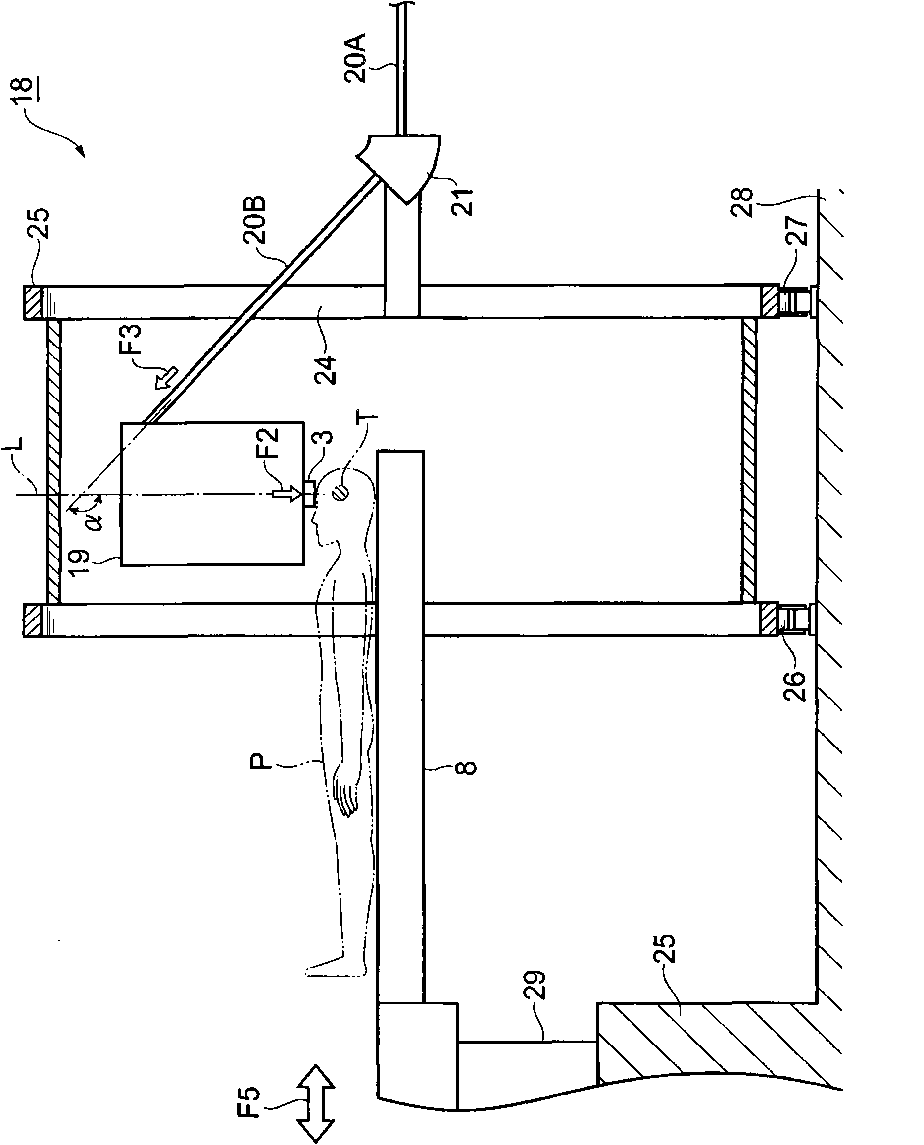
[0039] Such as image 3 as well as Figure 4 As shown, the difference between the neutron beam rotating irradiation device 18 in the second embodiment and the device 1 in the first embodiment lies in the angle α formed by the irradiation direction F3 of the ion beam to the target 7 and the emission direction F2 of neutrons. is 135°, and a deflection electromagnet 21 is provided. The other structures are the same as those of the device 1, and are assigned the same reference numerals here, and repeated descriptions are omitted.

[0040] Such as image 3 As shown, the neutron ray rotating irradiation device 18 has: a neutron generating part 19, which has a target 7 for generating neutrons by irradiating ion beams; a collimator 3, which is arranged on the exit side of the neutron generating part 19; a deflection electromagnetic The iron 21 deflects the ion beam irradiated to the target 7 , and the beam tubes 20 ( 20A, 20B) deliver the ion beam to the neutron generator 19 . The...

no. 3 Embodiment approach

[0044] Such as Figure 5 As shown, the difference between the neutron beam rotary irradiation device 23 in the third embodiment and the device 1 in the first embodiment is that the neutron beam is irradiated to the cancer cell T from a direction inclined with respect to the body axis of the patient P. The angle α formed by the irradiation direction F4 of the ion beam to the target 7 and the emission direction F2 of neutrons is 45°. The other structures are the same as those of the device 1, and are given the same reference numerals, and repeated descriptions are omitted. Furthermore, for example, when irradiating cancer cells T from a direction perpendicular to the body axis of the patient P, there may be a risk of damaging surrounding normal tissues. In addition to obtaining the same effects as those of the apparatus 1 of the first embodiment, since neutron rays can be irradiated to cancer cells T from a direction oblique to the body axis of the patient P, normal neutron ray...


PUM


Abstract

The invention provides a neutron ray rotary irradiation device which can realize miniaturization. The neutron ray rotary irradiation device (1) is provided with a neutron generating part (2), a speed reducing member (9), a collimator (3), two deflection electric magnets (4 and 5) and a beam tube (6), wherein the neutron generating part (2) is provided with a target (7) for generating a neutron through being irradiated by an ion beam; the speed reducing member (9) is used for reducing the speed of the neutron; the collimator (3) is arranged at the emergence side of the neutron generating part (2); the two deflection electric magnets (4 and 5) are used for making the ion beam deflected; and the beam tube (6) is used for conveying the ion beam. A communicating opening (10a) for communicating a target accommodating part (10) with the beam tube (6c) is arranged at a position lower than the top (10b) of the target accommodating part (10), and an angle alpha formed by the irradiation direction (F1) of the ion beam to the target (7) and the ejection direction (F2) of the neutron is 90 degrees.

Description

technical field [0001] The present invention relates to a neutron ray rotary irradiation device. Background technique [0002] Conventionally, as an apparatus for treating cancer in a patient, a charged particle beam apparatus for irradiating proton rays, baryon beams, etc. is known (for example, refer to Patent Document 1). This device has a pre-accelerator, a synchrotron accelerator, a rotary irradiation device, and a control device that controls emission from the pre-accelerator to the synchrotron accelerator, and transport of charged particle beams in the rotary irradiation device. However, in this rotary irradiation device, the charged particle beam emitted from the accelerator is deflected outward in the direction of the radius of rotation by the first deflection electromagnet, and then deflected outward in the direction of the radius of rotation by the second deflection electromagnet. The inside is deflected, and the deflection angle is an acute angle, so that the ma...

Claims


Application Information

Patent Timeline
Patent Type & Authority Applications(China)
IPC IPC(8): A61N5/10
Inventor 密本俊典
Owner SUMITOMO HEAVY IND LTD
Why Eureka
Try Eureka