Six-foot crawling robot

A crawling robot and robot technology, applied in the field of robotics, can solve the problems of a hexapod crawling robot with complex structure, simple control, and lack of human-controlled walking movements, and achieve the effects of simple structure, simple control, and reduced production costs

Inactive Publication Date: 2010-09-15
HARBIN INST OF TECH
View PDF5 Cites 20 Cited by
  • Summary
  • Abstract
  • Description
  • Claims
  • Application Information

AI Technical Summary

Problems solved by technology

[0003] The purpose of the present invention is to provide a hexapod crawling robot to solve the problems of the existing hexapod crawling robot with complex structure, simple control and lack of human-controlled walking movements.

Method used


Image

  • Six-foot crawling robot
  • Six-foot crawling robot
  • Six-foot crawling robot

Examples


specific Embodiment approach 1

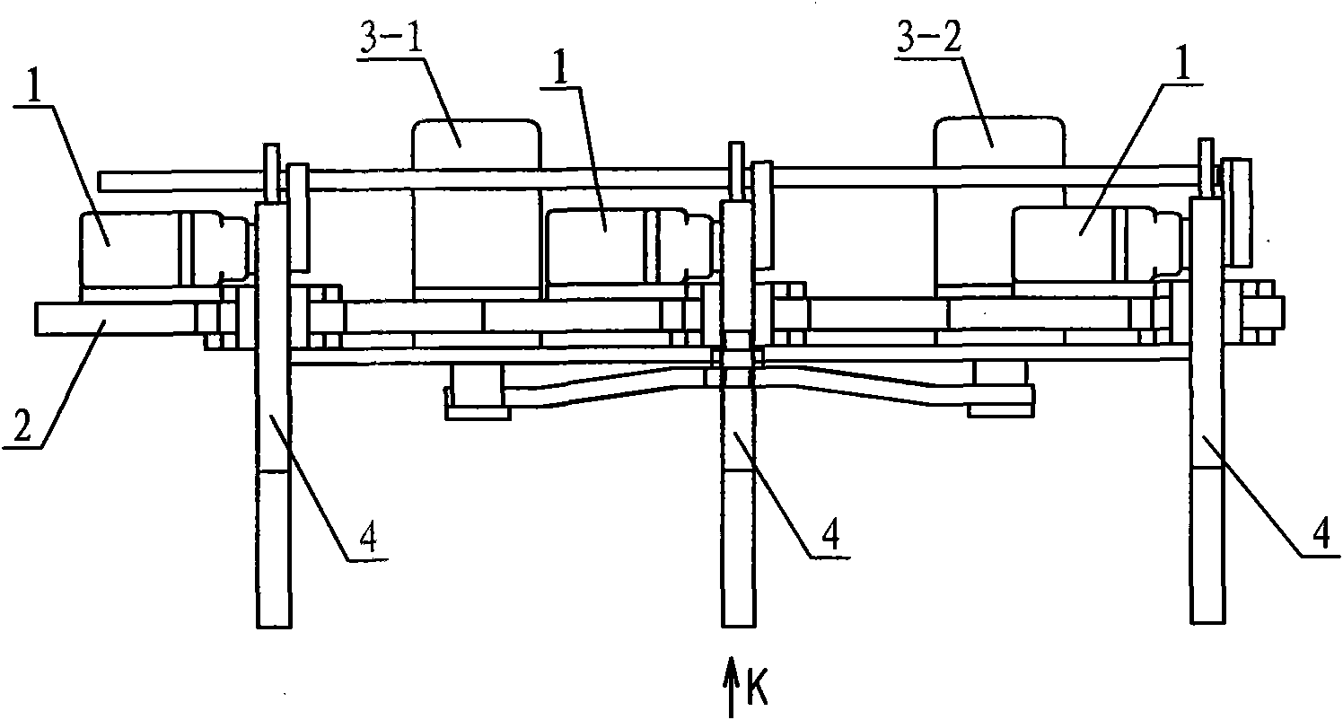
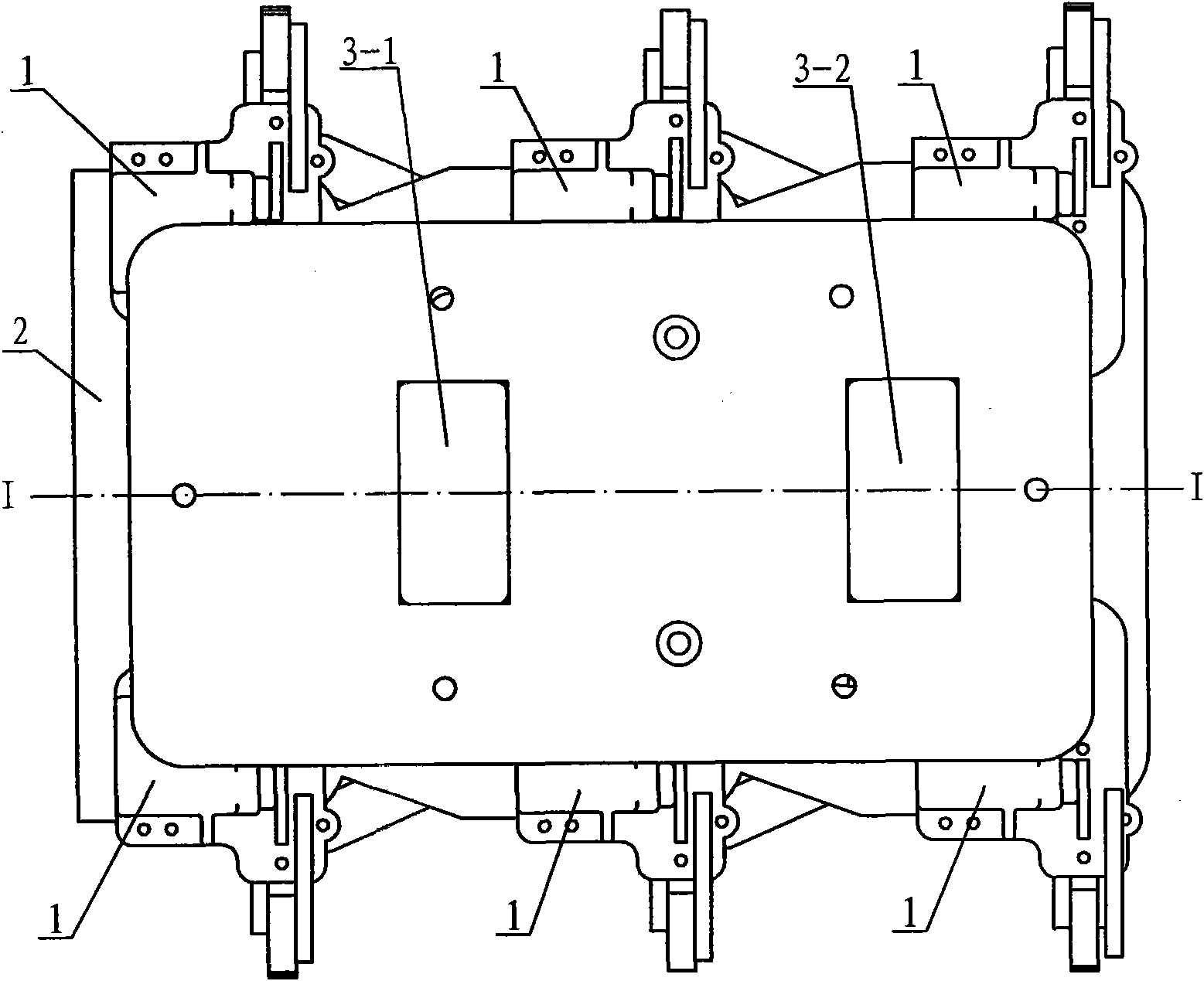
[0007] Specific implementation mode one: combine Figure 1 ~ Figure 4Describe this embodiment, this embodiment consists of six small steering gears 1, a main board 2, the first large steering gear 3-1, the second large steering gear 3-2, six foot mechanisms 4, and the first large steering gear pull rod 5 -1, the second largest steering gear pull rod 5-2, the first largest steering gear steering plate 6-1, the second largest steering gear steering plate 6-2, the first upper connecting plate 7-1, the second upper connecting plate 7 -2, the third upper connecting plate 7-3, the fourth upper connecting plate 7-4, the fifth upper connecting plate 7-5, the sixth upper connecting plate 7-6, the first connecting rod 8-1, the second connecting rod Rod 8-2, third connecting rod 8-3, fourth connecting rod 8-4, first lower connecting plate 9-1, second lower connecting plate 9-2, third lower connecting plate 9-3, fourth The lower connecting plate 9-4, the fifth lower connecting plate 9-5,...

specific Embodiment approach 2

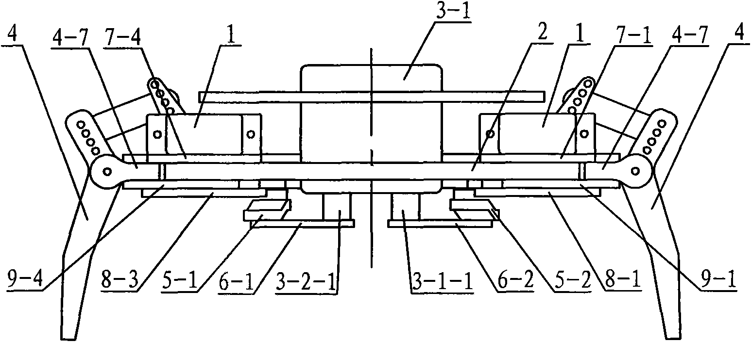
[0008] Specific implementation mode two: combination Figure 5 Describe this embodiment, each foot mechanism 4 of this embodiment is by the first connecting shaft 4-1, the second connecting shaft 4-2, the 3rd connecting shaft 4-3, pin 4-4, pin rod 4-5, Small steering wheel 4-6 and connecting seat 4-7 are composed, connecting seat 4-7 is hinged with pin 4-4 through first connecting shaft 4-1, pin 4-4 can rotate freely, pin 4-4 The upper end is hinged with an end of the second connecting shaft 4-2 and the pin rod 4-5, and the other end of the pin rod 4-5 is hinged with the small steering wheel 4-6 through the third connecting shaft 4-3. Other components and connections are the same as those in the first embodiment. Pin 4-4, pin pull bar 4-5, small steering wheel steering wheel 4-6 and connecting seat 4-7 constitute four-bar linkage. The small steering gear 1 drives the pin 4-4 through the small steering gear steering wheel 4-6 and the foot pull rod 4-5, thereby realizing the a...


PUM


Abstract

The invention relates to a robot, in particular to a six-foot crawling robot which aims at solving the problems that the existing six-foot crawling robot is complicated in structure, is simple to control and has no manual controlled walk action. A fourth lower connecting plate, a fifth lower connecting plate and a sixth lower connecting plate are driven to make leftward or rightward swinging by a first large steering engine through a first large steering engine tiller and a first large steering engine tension bar, and the fourth lower connecting plate, the fifth lower connecting plate and the sixth lower connecting plate respectively drive respective foot mechanism to operate to realize the leg striding action; in a similar way, a first lower connecting plate, a second lower connecting plate and a third lower connecting plate are driven to make leftward or rightward swinging by a second large steering engine through a second large steering engine tiller and a second large steering engine tension bar, and the first lower connecting plate, the second lower connecting plate and the third lower connecting plate respectively drive respective foot mechanism to operate to realize the leg striding action; and six small steering engines are used to respectively control the foot mechanism thereon to make leftward and rightward swinging to realize leftward or rightward turning.

Description

technical field [0001] The present invention relates to a robot. Background technique [0002] Two steering gears are installed on the parts of each leg of the existing hexapod crawling robot, so the whole hexapod crawling robot has 12 steering gears in total, and the structure is complex; in addition, the control of the robot is relatively simple, only need to turn on the switch, The robot can walk and cannot be manually intervened in the robot's movements, that is, it lacks the ability to artificially control the walking movement. Contents of the invention [0003] The object of the present invention is to provide a hexapod crawling robot to solve the problems that the existing hexapod crawling robot has complex structure, simple control and lack of human-controlled walking action. [0004] The present invention consists of six small steering gears, a main board, the first large steering gear, the second large steering gear, six foot mechanisms, the first large steering...

Claims


Application Information

Patent Timeline
Patent Type & Authority Applications(China)
IPC IPC(8): B62D57/032
Inventor 周定江王仕博肖长志陈定刘春来高海波
Owner HARBIN INST OF TECH
Why Eureka
Try Eureka