Roller type mechanical brake

A mechanical brake and roller type technology, applied in the direction of brake type, brake parts, mechanical equipment, etc., can solve the problems of inconvenience, short service life of brake components, etc., and achieve good impact reduction, good isolation of torsional vibration, and structural simple effect

Inactive Publication Date: 2010-09-15
陈伯恒
View PDF7 Cites 5 Cited by
  • Summary
  • Abstract
  • Description
  • Claims
  • Application Information

AI Technical Summary

Problems solved by technology

It can be seen that one of the main problems of this braking method is that the service life of the braking components is relatively short and frequent replacement is required, so it is relatively inconvenient

Method used


Image

  • Roller type mechanical brake
  • Roller type mechanical brake
  • Roller type mechanical brake

Examples


Embodiment Construction

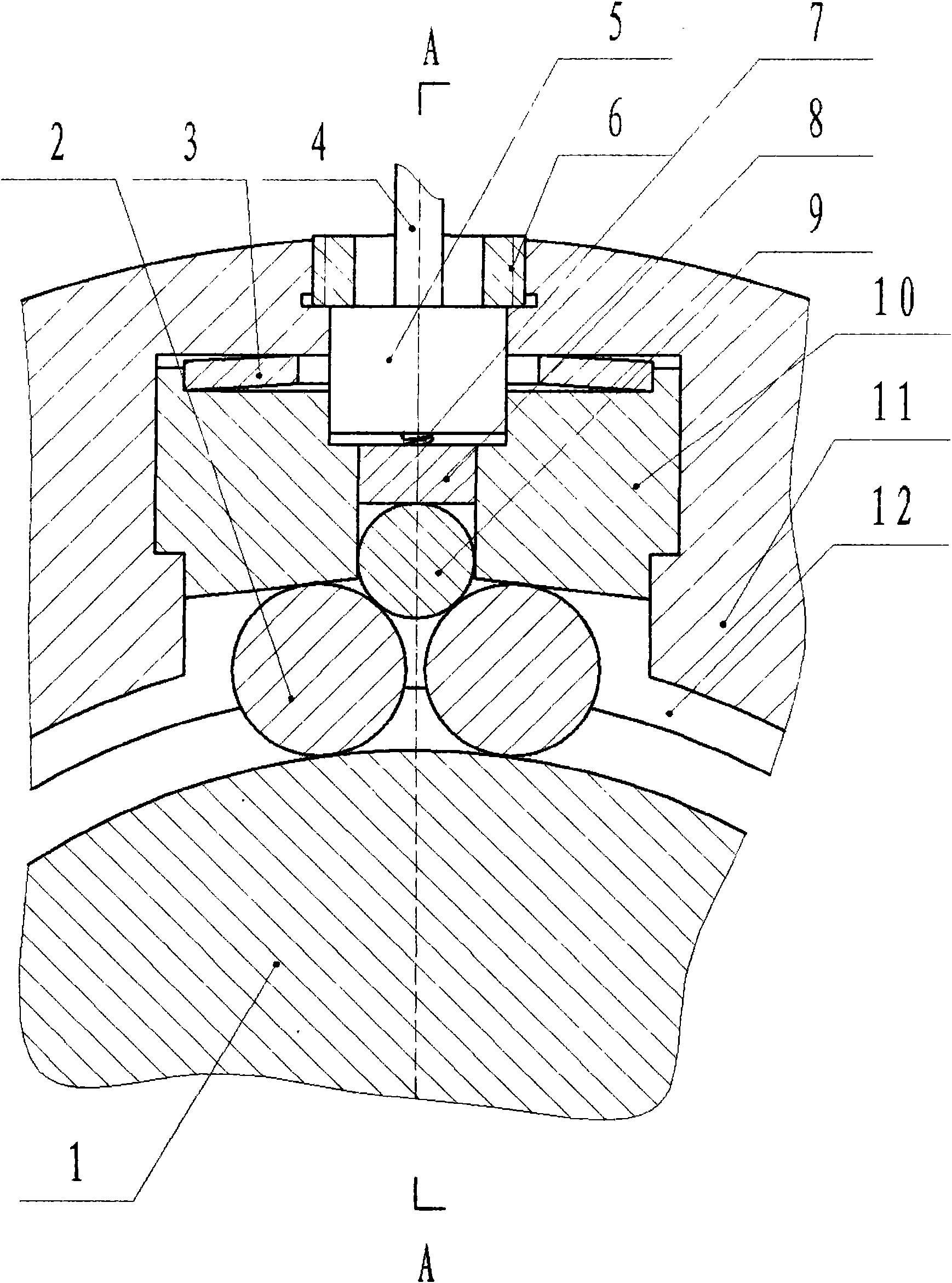
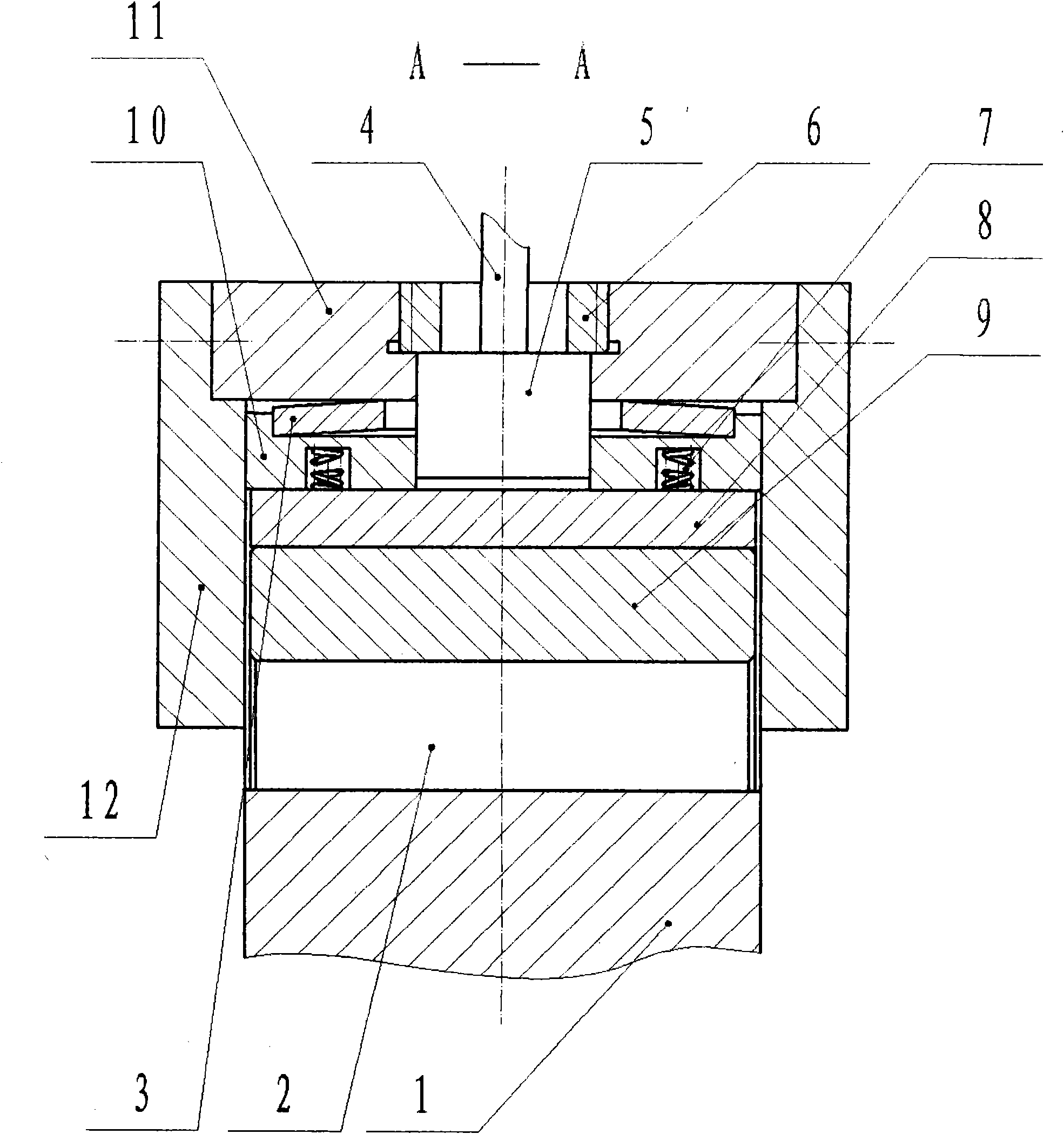
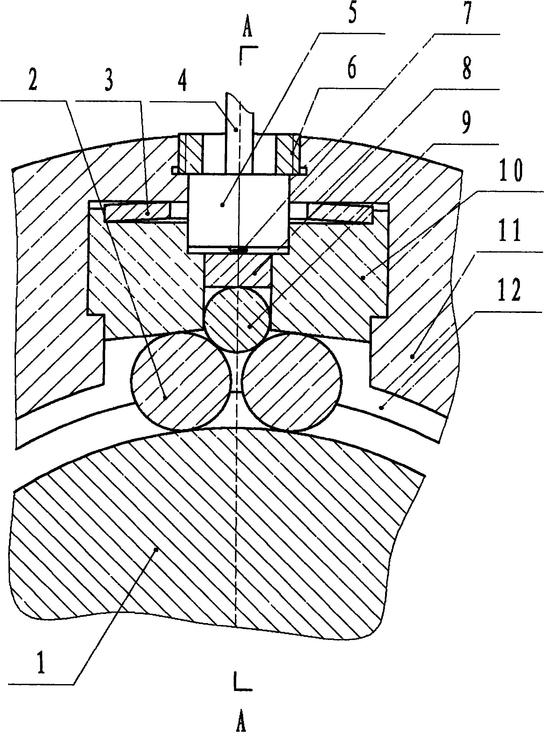
[0021] Below, the present invention will be further described in detail in conjunction with the accompanying drawings. exist figure 1 , figure 2 As can be seen in the figure, there is a roller type overrunning clutch mechanism in which the star wheel is an outer star wheel, and the feature is that the spring installed on the outer star wheel 11 in the roller type overrunning clutch mechanism in which the star wheel is an outer star wheel The pin ejector mechanism is removed, and a device installed near the position of the original spring pin ejector mechanism can perform constrained movement along the radial direction of the outer star wheel 11 and can tighten the roller 2 in the mechanism under the action of an operable external force. On the working position, the cylindrical roller top post 9 that can be disengaged from the roller 2 under the action of an operable external force is substituted.

[0022] In a roller mechanical brake, the working surfaces of the roller top ...


PUM


Abstract

The invention relates to a roller type mechanical brake belonging to the field of mechanical brakes and provided with a roller type overrunning clutch mechanism having a star wheel as an outer star wheel. The roller type mechanical brake is characterized in that a spring lifting pin mechanism installed on the outer star wheel (11) in the roller type overrunning clutch mechanism having the star wheel as the outer star wheel is removed and is replaced by a cylindrical roller lifting post (9) installed nearby the original spring lifting pin mechanism, wherein the cylindrical roller lifting post (9) can do constrained motion along the radial direction of the outer star wheel (11), lift a roller (2) in the mechanism on a working position under the action of operational external force and be separated from the roller (2) under the action of the operational external force.

Description

1. Technical field [0001] The invention relates to a roller type mechanical brake belonging to the field of mechanical brakes. 2. Background technology [0002] We know that in the mechanical field, the brake is a very important mechanical component, which is widely used in various mechanical industries. Taking the automotive field as an example, the importance of brakes is obvious. [0003] However, we also know that the brakes currently used in automobiles are almost all of the mechanical surface friction type, which uses the braking torque generated by the friction between the two working surfaces of the rotating element and the fixed element to slow down or stop the car. It can be seen that a major problem of this braking method is that the service life of the braking components is relatively short and requires frequent replacement, so it is relatively inconvenient. 3. Contents of the invention [0004] The purpose of the present invention is to propose a principle t...

Claims


Application Information

Patent Timeline
Patent Type & Authority Applications(China)
IPC IPC(8): F16D63/00F16D65/21F16D65/20F16D65/18
Inventor 陈伯恒
Owner 陈伯恒
Why Eureka
Try Eureka