A new energy vehicle wheel side motor drive axle

A new energy vehicle, wheel motor technology, applied in the direction of brakes, braking components, vehicle parts, etc., can solve the problems of large space occupation, low braking efficiency, high braking noise, etc., to solve the installation problem, improve the system. Dynamic efficiency and low braking noise

Active Publication Date: 2016-02-10
JASMIN INT AUTO RES ANDDEV BEIJING CO LTD
View PDF6 Cites 3 Cited by
  • Summary
  • Abstract
  • Description
  • Claims
  • Application Information

AI Technical Summary

Problems solved by technology

[0003] At present, the structure of most new energy vehicle drive systems is that the central motor is connected to a traditional rear axle through the transmission shaft. This way of transmission efficiency is poor and the system is complicated. However, the drive axle structure of wheel motors has become a research topic at home and abroad. Important direction, the drive axle of this structure generally includes the drive motor, reducer mechanism, wheel hub and other components, instead of the engine, clutch, gearbox, drive shaft, differential, wheel hub assembly and other components, which simplifies the overall mechanism and improves transmission efficiency
[0004] However, most of the existing foreign wheel-side motor drive axles are heavy-duty axles suitable for vehicles with a load of more than eight tons, and the scope of application is relatively narrow. The brakes used are air brakes. The braking time is longer, the braking noise is louder, and it is difficult to meet the low-noise requirements of light-duty high-end passenger cars, and the existing wheel-side motor drive axle has a large change in structure compared with the traditional drive system, and the traditional parking brake The installation method cannot be applied to the existing wheel side motor drive axle, so the existing wheel side motor drive axle lacks a parking brake so that its overall braking efficiency is relatively low

Method used


Image

  • A new energy vehicle wheel side motor drive axle
  • A new energy vehicle wheel side motor drive axle
  • A new energy vehicle wheel side motor drive axle

Examples


Embodiment Construction

[0027] The specific implementation manners of the present invention will be further described in detail below in conjunction with the accompanying drawings and examples. The following examples are used to illustrate the present invention, but are not intended to limit the scope of the present invention.

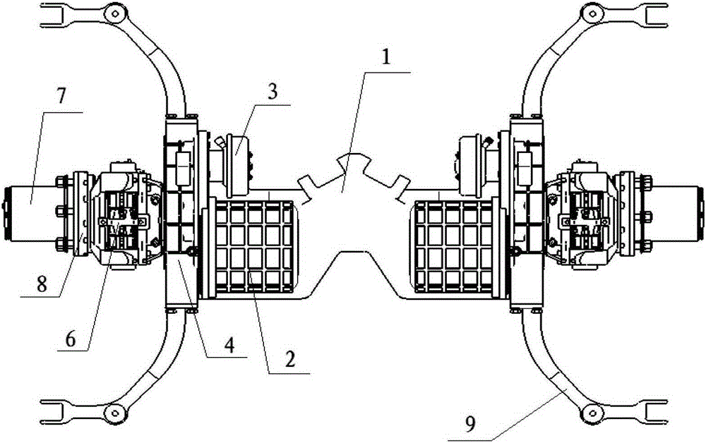
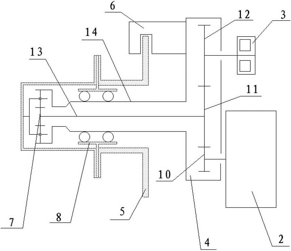
[0028] Such as figure 1 with figure 2 As shown, the new energy vehicle wheel motor drive axle provided by the present invention includes a beam assembly 1, two driving motor assemblies 2 and two primary reducer assemblies are symmetrically arranged on the left and right sides of the beam assembly 1 4. Two secondary reducer assemblies 7, two hub assemblies 8, two hydraulic brake assemblies 6, two parking brake assemblies 3 and four suspension support arm assemblies 9.

[0029] The beam assembly 1 is connected to the inner side of the housing of the first-stage reducer assembly 4, and the housing of the first-stage reducer assembly 4 has a motor-driven input gear 10, an outp...


PUM


Abstract

The invention relates to the field of new energy automobiles, in particular to a wheel motor drive axle of a new energy automobile. The wheel motor drive axle comprises a cross beam assembly, and wheel motor driving systems horizontally and symmetrically arranged at the two sides of the cross beam assembly, wherein each wheel motor driving system comprises a driving motor assembly, a first-stage speed reducer assembly, a second-stage speed reducer assembly, a wheel hub assembly, a hydraulic brake assembly and a parking brake assembly; and hydraulic brakes are arranged on shells or axle shaft sleeves of the first-stage speed reducer assemblies of the wheel motor driving systems and fit brake discs arranged on wheel hubs for realizing hydraulic braking of the wheel hubs, so that the braking response is quick and the braking noise is low. Thus, the wheel motor drive axle can satisfy the braking requirements of a light top-grade passenger car. A hydraulic braking mode is adopted, so that the whole drive axle is compact in structure and is small in occupied space.

Description

technical field [0001] The invention relates to the field of new energy vehicles, in particular to a new energy vehicle wheel motor drive axle. Background technique [0002] With the gradual withering of oil resources and the gradual increase of air pollution, the society is increasingly calling for new energy vehicles, including pure electric, hybrid, plug-in, fuel cell and other forms of vehicles. New energy vehicles greatly reduce the impact on Oil dependence and air pollution. Compared with traditional internal combustion engine vehicles, new energy vehicles have undergone tremendous changes in both the general layout of the vehicle and the drive system assembly due to the different forms of energy supply. The drive system assembly is crucial to the vehicle. Important, it not only undertakes the carrying function and driving function, but also directly determines the safety and comfort performance of the vehicle. [0003] At present, the structure of most new energy ve...

Claims


Application Information

Patent Timeline
Patent Type & Authority Patents(China)
IPC IPC(8): B60T1/06
CPCB60T1/062
Inventor 陈言平崔普金雷继斌
Owner JASMIN INT AUTO RES ANDDEV BEIJING CO LTD
Why Eureka
Try Eureka