Supercharge Your Innovation With Domain-Expert AI Agents!

Differential pressure valve

A technology of differential pressure valve and valve body, which is applied in the field of valves and differential pressure valves. It can solve the problems affecting the normal use and deflection of pressure reducing valves, and achieve the effects of simple structure, increased stability, and avoiding premature damage.

Inactive Publication Date: 2010-09-15
卓旦春
View PDF7 Cites 9 Cited by
  • Summary
  • Abstract
  • Description
  • Claims
  • Application Information

AI Technical Summary

Problems solved by technology

[0004] It can be seen that there is no mechanism to guide the disc during the movement of the valve disc in the above pressure reducing valve, and the valve disc may be deflected during the movement process, thus affecting the normal use of the pressure reducing valve

Method used


Image

  • Differential pressure valve
  • Differential pressure valve
  • Differential pressure valve

Examples


Embodiment Construction

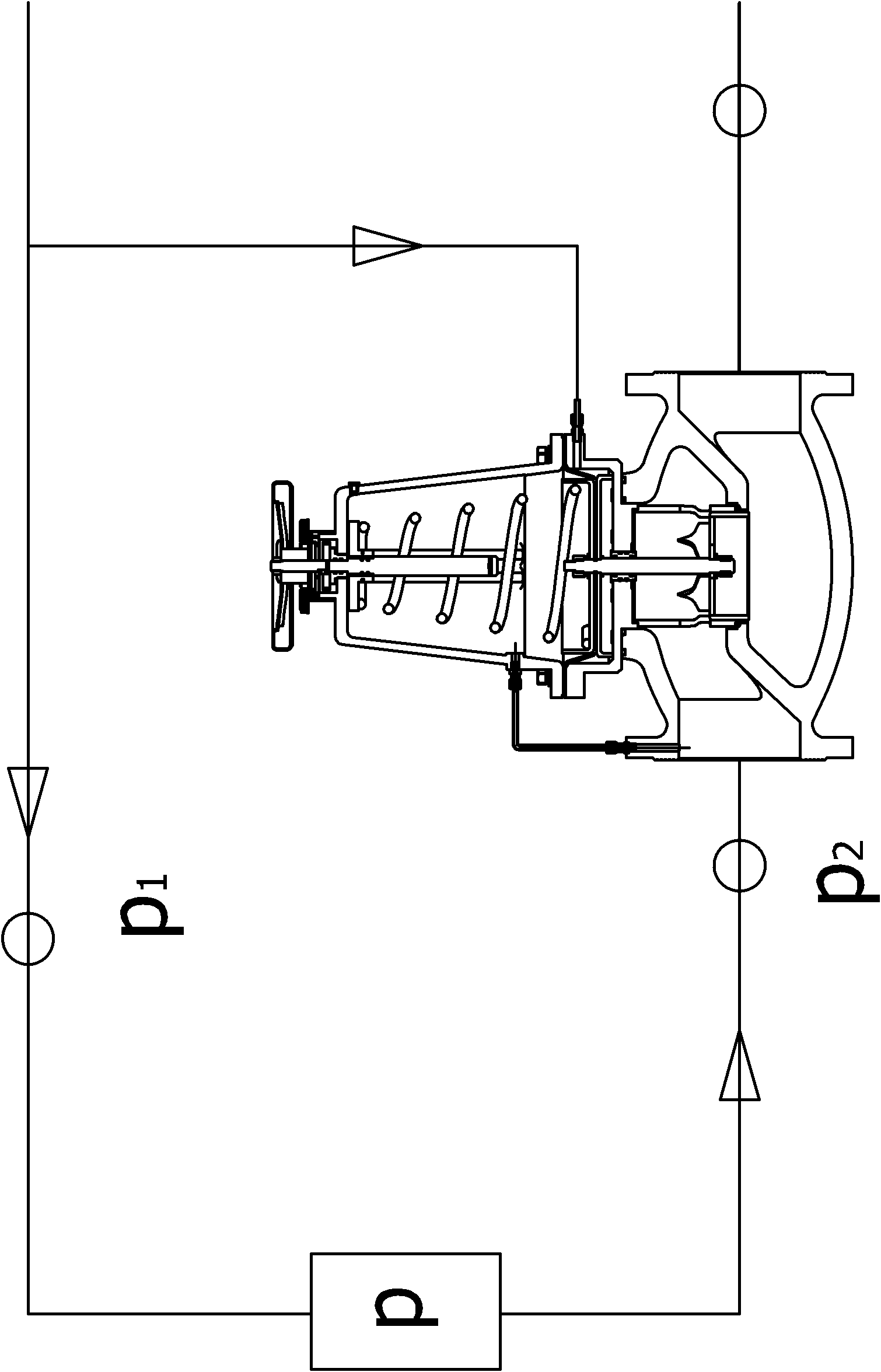
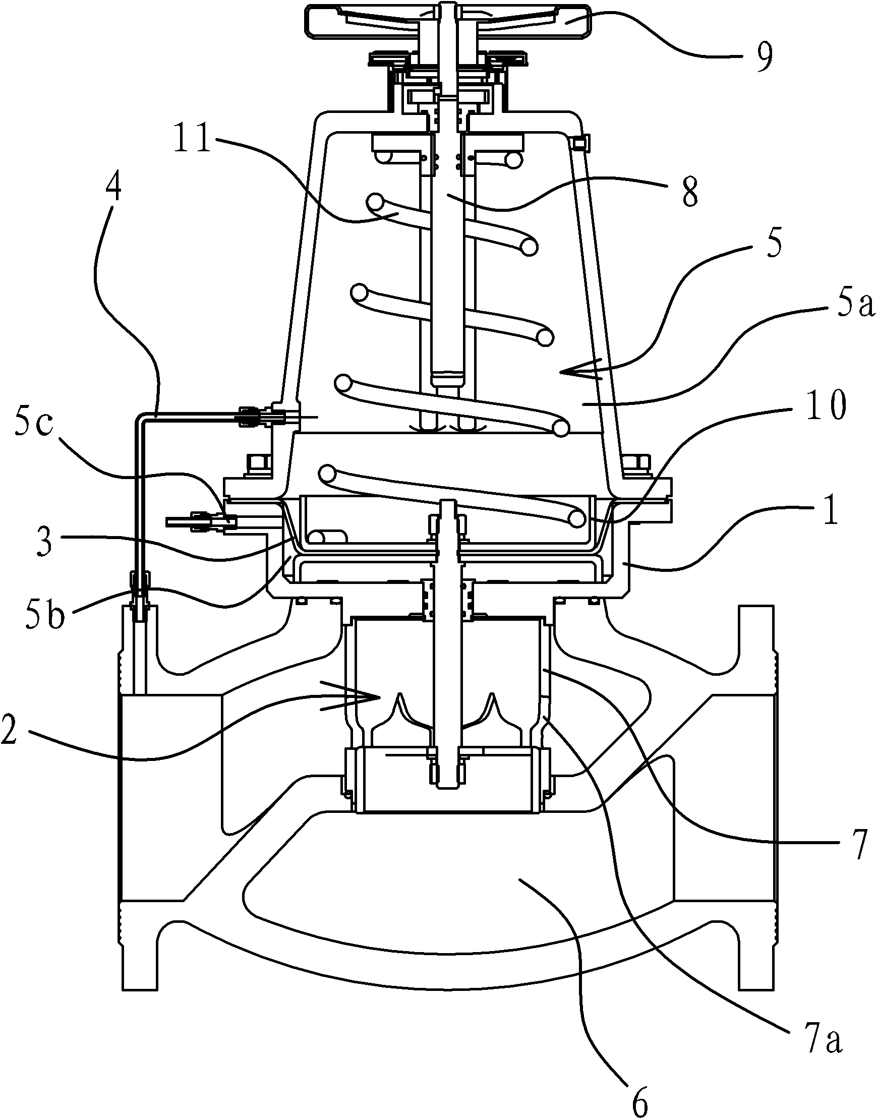
[0041] Such as figure 1 As shown, the differential pressure valve includes a valve body 1 with a cavity inside, a valve core 1 , a spring 11 , a diaphragm 3 , a pressure guide tube 4 and a connecting cylinder 7 located in the valve body 1 .

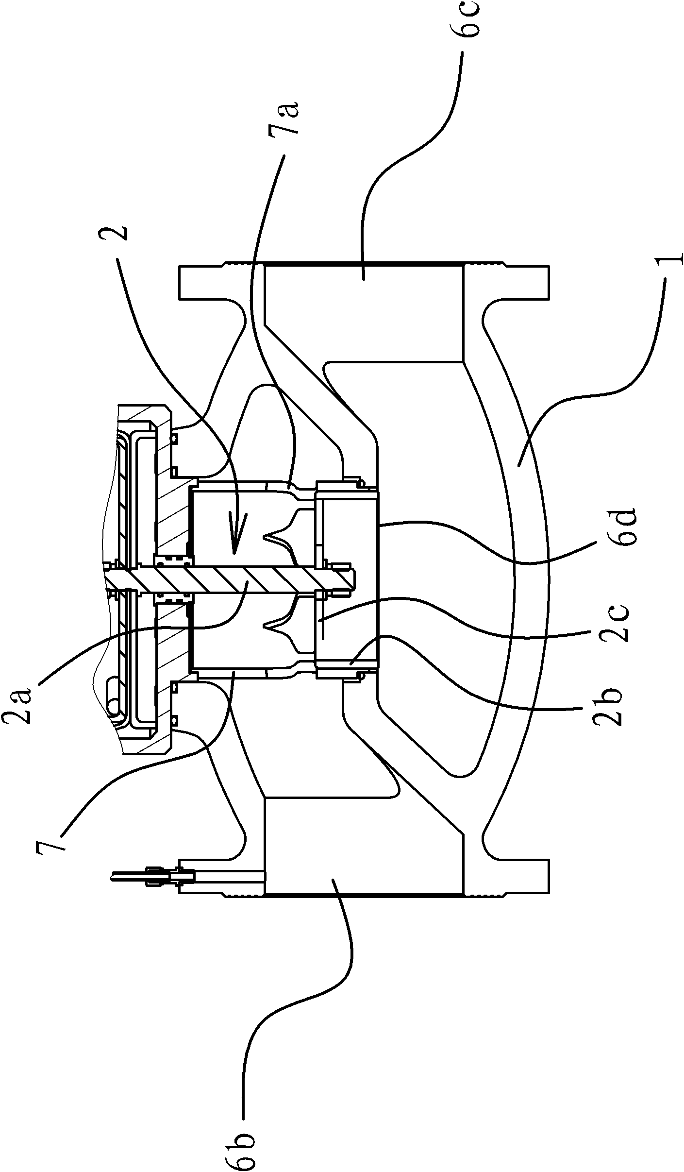
[0042] Such as figure 1 with figure 2 As shown, the valve body 1 has two chambers adjacent up and down: the control chamber 5 and the water passage chamber 6 . The diaphragm 3 is arranged in the control chamber, and the diaphragm 3 divides the control chamber 5 into a balance chamber 1 5 a and a balance chamber 2 5 b adjacent up and down. The second balance chamber 5b has a pressure guiding port 5c connected thereto.

[0043] The spring 11 is arranged in the first balance chamber 5a, and the two ends of the spring 11 act on the inside of the valve body 1 and the diaphragm 3 respectively.

[0044] The spool 2 is composed of a piston 2b and a connecting rod 2a. One end of the connecting rod 2a passes through the balance chamber 2 5b an...


PUM


Abstract

The invention provides a differential pressure valve which belongs to the technical field of machinery, solving the problem of low use stability of the traditional pressure-reducing valves. The differential pressure valve comprises a valve body and a valve element, wherein the valve body is internally provided with a control cavity and a water-through cavity which are adjacent up and down; the control cavity is internally provided with a diaphragm dividing the control cavity into a balancing cavity 1 and a balancing cavity 2 which are adjacent up and down; the balancing cavity 1 is internally provided with a spring, and both ends of the spring respectively act on the valve body and the diaphragm; one end of the valve element passes through the balancing cavity 2 and is connected with the diaphragm, while the other end of the valve element is arranged in the water-through cavity; the balancing cavity 2 is provided with a pressure guidance port used for communicating with a water inlet end of a user; and a variable mechanism capable of reducing the opening degree of the differential pressure valve through the action of the valve element when pressure in the balancing cavity 2 increases is arranged between the other end of the valve element and the water-through cavity. Because a connecting cylinder playing a role of guiding is arranged in the water-through cavity, the valve element of the differential pressure valve can stably move in the process of use, thereby increasing the stability of the differential pressure valve.

Description

technical field [0001] The invention belongs to the technical field of machinery and relates to a valve, in particular to a differential pressure valve. Background technique [0002] The differential pressure valve is a self-operated differential pressure balance valve, which automatically adjusts depending on the pressure change of the fluid medium itself, automatically eliminates the residual pressure of the pipeline and the flow deviation caused by pressure fluctuations, and keeps the pressure difference between the user's water inlet and outlet. Differential pressure valve is especially suitable for household metering or automatic control system, which helps to stabilize the system operation. [0003] For example, the Chinese patent CN201386795Y provides "a piston-type multi-nozzle pressure reducing valve", which includes a valve body, a valve stem, a valve disc, and a piston. There is a spring between the valve body and the lower part of the piston is fixedly connected...

Claims


Application Information

Patent Timeline
IPC IPC(8): F16K3/24F16K3/316F16K17/22F16K31/126
Inventor 卓旦春
Owner 卓旦春
Features
  • R&D
  • Intellectual Property
  • Life Sciences
  • Materials
  • Tech Scout
  • Unparalleled Data Quality
  • Higher Quality Content
  • 60% Fewer Hallucinations
Learn More