
Device for carrying out long-time continuous optical monitoring on liquid concentration

A technology for optical monitoring and liquid concentration, which is applied in measuring devices, color/spectral characteristic measurement, material analysis through optical means, etc. It can solve the problems of poor practicability and applicability, unsuitability for long-term continuous monitoring of liquid concentration, and short calibration period and other problems, to achieve the effect of eliminating the interference of slow-changing factors and continuously monitoring the liquid concentration for a long time

Inactive Publication Date: 2010-09-15
ZHEJIANG UNIV
View PDF5 Cites 0 Cited by
  • Summary
  • Abstract
  • Description
  • Claims
  • Application Information

AI Technical Summary

Problems solved by technology

However, due to the aging effect of the light source, the slow drift of the emitted light intensity will inevitably be caused, and the aging and corrosion of the lenses at the transmitting end and the receiving end will cause errors in the detection of the received light intensity.
Therefore, it is not suitable for long-term continuous monitoring of liquid concentration
In addition, traditional spectrophotometric detection equipment must be calibrated regularly to ensure the accuracy and reliability of test results
Regular offline calibration will inevitably interrupt the continuity of detection. If the calibration cycle is short and frequent, the practicability and applicability will be poor; if the calibration cycle is long, the detection accuracy cannot be guaranteed.

Method used


Image

  • Device for carrying out long-time continuous optical monitoring on liquid concentration
  • Device for carrying out long-time continuous optical monitoring on liquid concentration
  • Device for carrying out long-time continuous optical monitoring on liquid concentration

Examples


Embodiment Construction

[0020] The structure of the present invention will be further described below in conjunction with the drawings and embodiments.

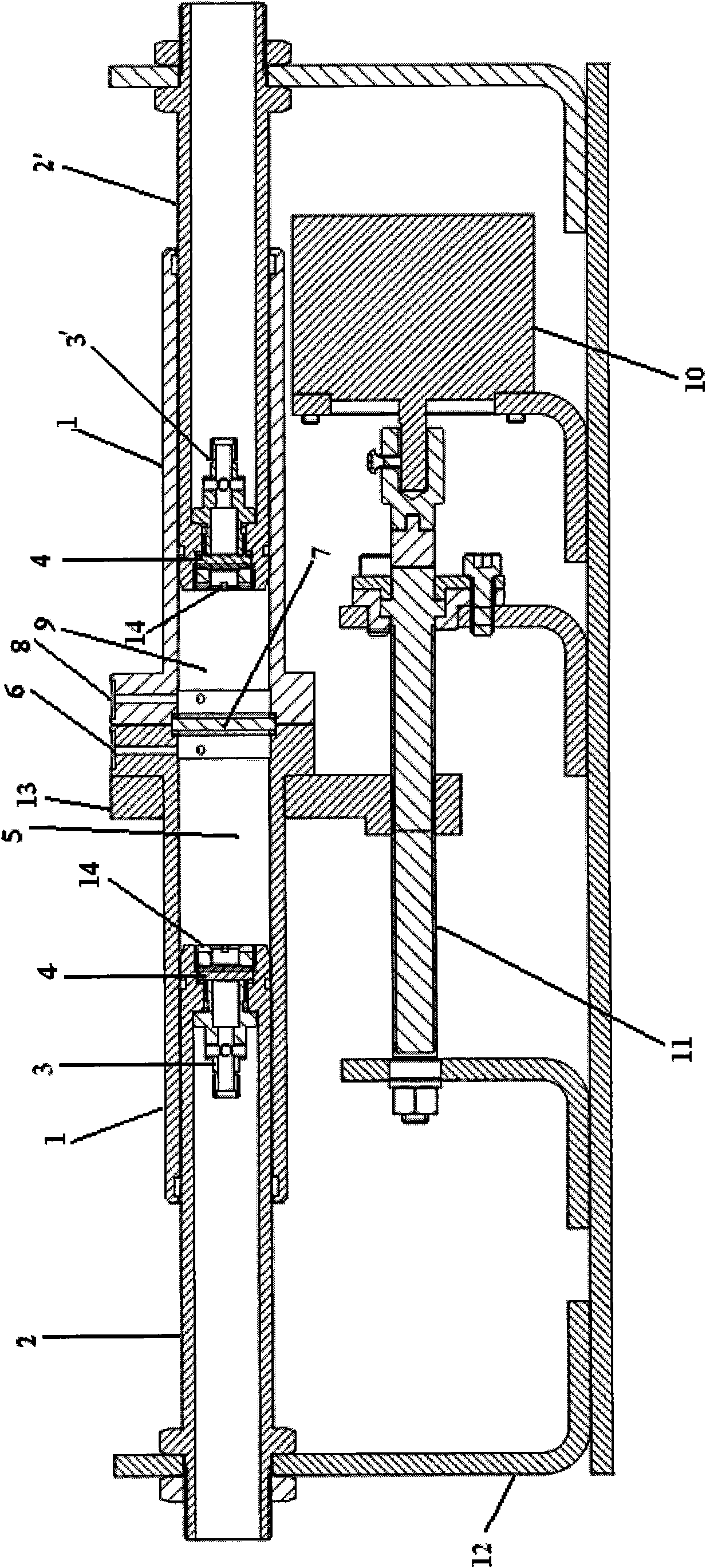
[0021] Such as figure 1 In the device of the present invention shown, the movable sleeve 1 has a cylindrical structure, and the first plunger 2 and the second plunger 2'are partially placed in the movable sleeve 1. The inner diameter of the movable sleeve 1 is matched with the outer diameters of the first plunger 2 and the second plunger 2', so that the first plunger 2 and the second plunger 2'can be connected to the movable sleeve through a ○-shaped sealing ring. 1 forms a dynamic seal, and a fixed cavity is enclosed between the movable sleeve 1 and the first plunger 2 and the second plunger 2'.

[0022] The transparent lens 7 is sealed and fixed in the movable sleeve 1, so that the first plunger 2 and the second plunger 2'are respectively located on both sides of the transparent lens 7, thereby connecting the movable sleeve 1 with the first plunger 2 a...


PUM


Abstract

The invention discloses a device for carrying out long-time continuous optical monitoring on liquid concentration, which is characterized in that a movable sleeve is internally hermetically fixed with a light-transmitting lens and provided with a first plunger piston and a second plunger piston; the first plunger piston and the second plunger piston are respectively positioned at both sides of the light-transmitting lens and form dynamical seal with the movable sleeve; cavities of the first plunger piston and the second plunger piston are respectively internally hermetically fixed with a plunger piston lens, and the central axes of the two plunger piston lenses are coincided; the outer ends of the first plunger piston and the second plunger piston are respectively fixedly connected with a fixed supporting seat; the length of the movable sleeve is more than double longer than the distance between the plunger piston lens of the first plunger piston and the plunger piston lens of the second plunger piston; a reference solution cavity is formed between the inner end surface of the plunger piston lens of the first plunger piston and the light-transmitting lens, and a solution (to be measured) cavity is formed between the inner end surface of the plunger piston lens of the second plunger piston and the light-transmitting lens; the wall of the movable sleeve is provided with a solution (to be measured) injection / discharge port and a reference solution injection / discharge port, and the solution (to be measured) injection / discharge port and the reference solution injection / discharge port are correspondingly communicated with the solution (to be measured) cavity and the reference solution cavity.

Description

Technical field [0001] The invention relates to an optical analysis instrument, in particular to an optical detection device for monitoring liquid concentration. Background technique [0002] The traditional optical detection principle is based on the Lambert-Beer law, which detects the intensity of the emitted light and the received light, and determines the concentration of the analyte according to parameters such as the absorption constant and the optical path. However, the aging effect of the light source will inevitably cause the slow drift of the emitted light intensity, and the aging and corrosion of the emitting end and the receiving end lens will cause errors in the received light intensity detection. Therefore, it is not suitable for long-term continuous monitoring of liquid concentration. In addition, traditional spectrophotometric testing equipment must be calibrated regularly to ensure the accuracy and reliability of testing results. Regular offline calibration is ...

Claims


Application Information

Patent Timeline
IPC IPC(8): G01N21/31G01N21/01
Inventor 叶树明蒋凯朱凡汤亚伟
Owner ZHEJIANG UNIV
Learn More