
Coupler and power amplification system

A power amplifier system and coupler technology, applied in the field of communication, can solve the problems of wasting wiring space, increasing link insertion loss, long wiring links, etc., and achieve the effect of reducing wiring space and reducing insertion loss

Inactive Publication Date: 2010-09-15
HUAWEI TECH CO LTD
View PDF6 Cites 5 Cited by
  • Summary
  • Abstract
  • Description
  • Claims
  • Application Information

AI Technical Summary

Problems solved by technology

[0004] There is no coupler with impedance changing function in the prior art. When impedance transformation and coupling power are required at the same time, the coupler and impedance transformer are connected in series, which will cause a long wiring link and waste wiring space. , increasing the insertion loss of the link

Method used

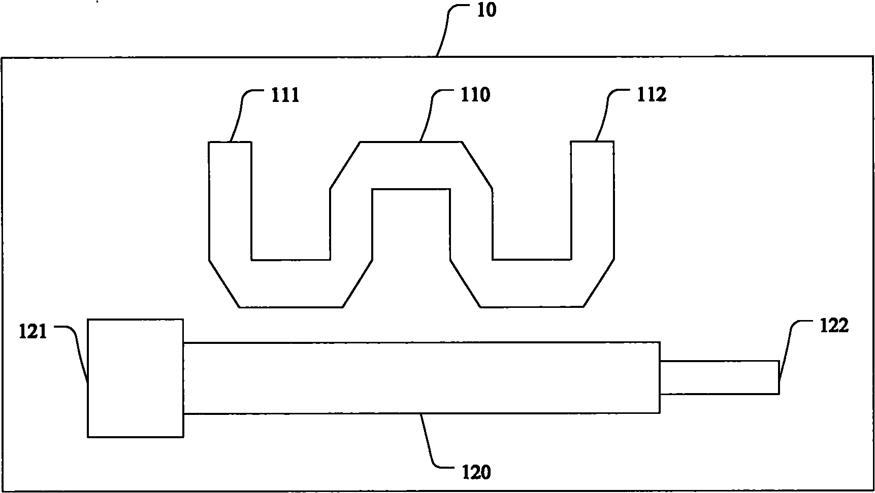
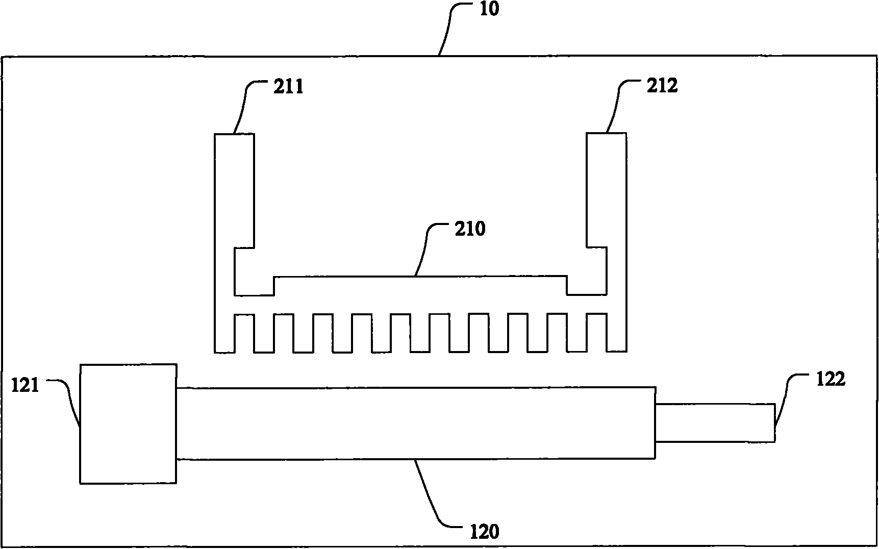

Image

  • Coupler and power amplification system
  • Coupler and power amplification system
  • Coupler and power amplification system

Examples


Embodiment Construction

[0021] The technical solutions in the embodiments of the present invention will be clearly and completely described below in conjunction with the accompanying drawings in the embodiments of the present invention. Obviously, the described embodiments are only a part of the embodiments of the present invention, rather than all the embodiments. Based on the embodiments of the present invention, all other embodiments obtained by those of ordinary skill in the art without creative work shall fall within the protection scope of the present invention.

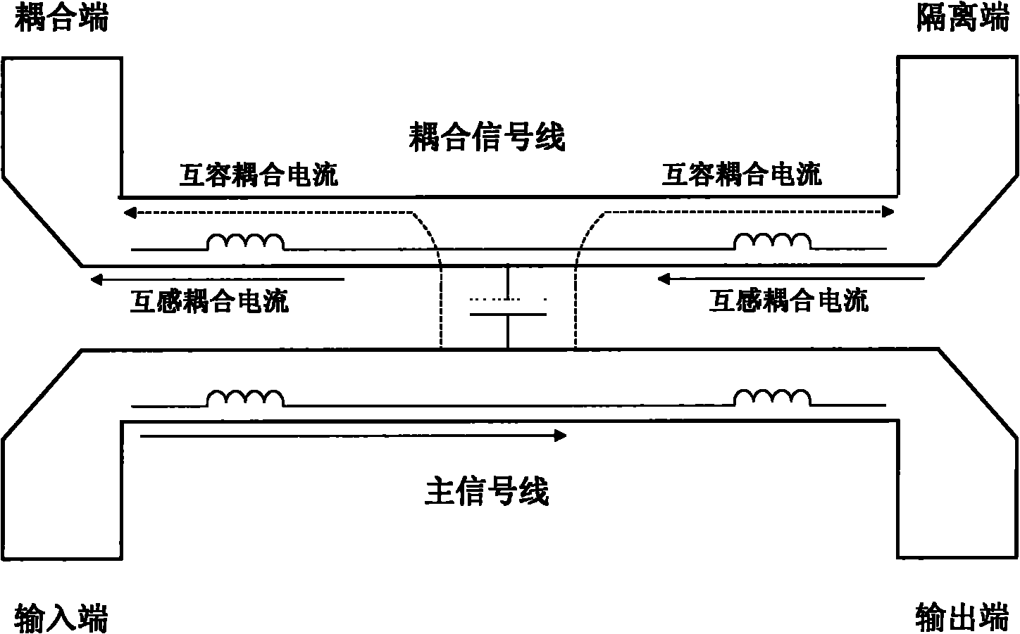
[0022] In order to enable those of ordinary skill in the art to better understand the present invention, the embodiment of the present invention first introduces the basic principle of the coupler. figure 1 It is a schematic diagram of the basic principle of the coupler provided by the embodiment of the present invention. Such as figure 1 As shown, the conventional coupler is composed of a main signal line and a coupled signal line that a...


PUM


Abstract

The embodiment of the invention provides a coupler and a power amplification system. A main signal wire of the coupler is an impedance conversion wire. The power amplification system comprises a power amplification module and the coupler, wherein the main signal wire of the coupler is the impedance conversion wire; and the coupler is connected with the power amplification module through the main signal wire and used for coupling high-power signals output by the power amplification module and converting the output impedance of the power amplification module into preset impedance required for the system. The coupler of the embodiment of the invention has the functions of impedance conversion and power coupling at the same time, can be applied to the system which needs impedance conversion and power coupling at the same time, can reduce the wiring space of the system, and has little link plug-in loss of the system.

Description

Technical field [0001] The present invention relates to the field of communication, in particular to a coupler and a power amplifier system. Background technique [0002] With the intensification of competition in the communications industry, low-cost, high-performance, and miniaturized product solutions have increasingly become an inevitable trend to seize market opportunities and make profits. With the development of mobile communications, couplers are widely used in radio frequency and microwave systems for signal power distribution and synthesis, power sampling and detection. A typical coupler is actually a four-port network that divides the input signal into two output signals with a specific ratio of power within a specific frequency range. Similarly, the reverse use has the effect of power synthesis. There are many types of couplers, each with its own characteristics, the most common is the parallel line coupler [0003] Many power amplifier systems nowadays often need to ...

Claims


Application Information

Patent Timeline
Patent Type & Authority Applications(China)
IPC IPC(8): H01P5/00H03F3/60
CPCH01P5/185
Inventor 余铁柱于乔利
Owner HUAWEI TECH CO LTD
Learn More