Single pole single throw RF switch and single pole multi throw RF switch based on single pole single throw RF switch

A radio frequency switch, single-pole single-throw technology, applied in the field of integrated circuits, can solve the problems of large volume, large insertion loss, long switch response time, etc., and achieve the effect of fewer circuit components, high isolation, and reduced layout area

Pending Publication Date: 2018-09-25
KANGXI COMM TECH SHANGHAI CO LTD
View PDF10 Cites 1 Cited by
  • Summary
  • Abstract
  • Description
  • Claims
  • Application Information

AI Technical Summary

Problems solved by technology

In the current microwave communication system, the power switch usually adopts several forms: (1) It adopts discrete silicon PIN diodes, which are implemented in the form of hybrid circuits. The disadvantages are large volume, narrow operating frequency and complex control circuits.
(2) Gallium arsenide (GaAs) high electron mobility transistor (pHEMT) monolithic switch is used. The high electron mobility transistor switch has the characteristics of small size and wide application frequency band. However, it is not easy to make a single chip with other radio frequency circuits. to integrate
(3) The switch using MOS devices has a price advantage and is suitable for on-chip integration with other communication circuits. The disadvantage is that the ability to withstand voltage and high power is limited
In addition, the existing power switches urgently need to overcome the shortcomings of large insertion loss, unsatisfactory isolation, large input-output standing wave ratio, and long switch response time. With the continuous development of modern communication technology and people's requirements for communication quality Increasingly demanding, the traditional power switch can no longer meet the needs of actual use

Method used


Image

  • Single pole single throw RF switch and single pole multi throw RF switch based on single pole single throw RF switch
  • Single pole single throw RF switch and single pole multi throw RF switch based on single pole single throw RF switch
  • Single pole single throw RF switch and single pole multi throw RF switch based on single pole single throw RF switch

Examples


Embodiment Construction

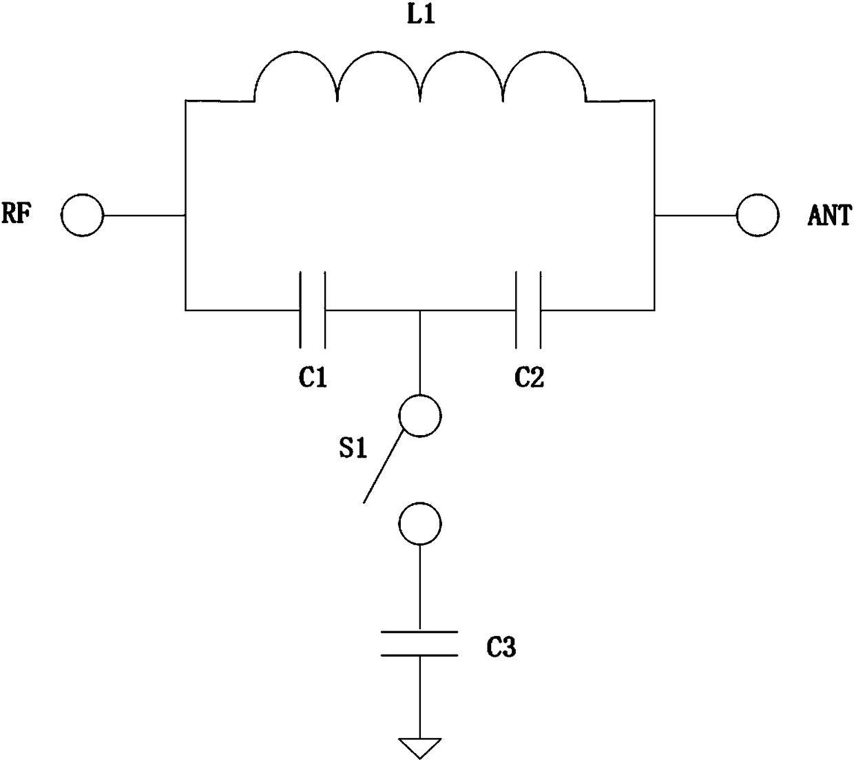
[0032] like figure 1 As shown, an embodiment of the single-pole single-throw radio frequency switch of the present invention includes: an inductor L1, first to third capacitors C1 to C3, and a switching device S1;

[0033] The inductor L1 is connected between the radio frequency terminal RF and the antenna terminal ANT, the first capacitor C1 and the second capacitor C2 are connected in series between the radio frequency terminal RF and the antenna terminal ANT and are connected in parallel with the inductor L1; one end of the switching device S1 is connected to the first capacitor Between C1 and the second capacitor C2, the other end is grounded through the third capacitor C3.

[0034] Wherein, the switch device S1 is PMOS, NMOS, HEMT or LDMOS.

[0035] Wherein, when the switching device S1 is off, the working state of the SPST radio frequency switch is off; when the switching device S1 is on, the working state of the SPST radio frequency switch is on.

[0036] Wherein, th...


PUM


Abstract

The invention discloses a single pole single throw RF switch. The switch comprises an inductor, a first capacitor, a second capacitor, a third capacitor and a switch device, wherein the inductor is connected between an RF end and an antenna end, the first capacitor and the second capacitor are connected between the RF end and the antenna end in serial and are connected with the inductor in parallel, one end of the switch device is connected between the first capacitor and the second capacitor, and the other end thereof is grounded through the third capacitor. The invention further discloses asingle pole multi throw RF switch. Compared with the existing single pole single throw RF switch/single pole multi throw RF switch, the single pole single throw RF switch/single pole multi throw RF switch of the invention is further isolated when being switched off, is more flexible in impedance transform when being switched on, uses fewer circuit elements, and reduces layout area of a semiconductor chip.

Description

technical field [0001] The invention relates to the field of integrated circuits, in particular to a single-pole single-throw radio frequency switch. The present invention also relates to a single-pole multi-throw radio frequency switch composed of the single-pole single-throw radio frequency switch. Background technique [0002] With the in-depth development of modern communication technology, communication equipment is developing towards miniaturization and low energy consumption, which requires each component in communication equipment to adopt a miniaturized design, try to control the size and thickness of the device, and at the same time minimize the number of components and Component power consumption. [0003] The RF signal input and output module can mainly realize the functions of low-noise amplification of the received RF signal and power amplification of the transmitted RF signal. It is an indispensable part of the RF communication equipment. Among them, the SPST...

Claims


Application Information

Patent Timeline
Patent Type & Authority Applications(China)
IPC IPC(8): H03K17/687
CPCH03K17/687
Inventor 赵奂何山暐
Owner KANGXI COMM TECH SHANGHAI CO LTD
Why Eureka
Try Eureka