Voltage-controlled magnetic impedance transformer

An impedance converter and magnetic technology, applied in waveguide devices, electrical components, connecting devices, etc., can solve the problems of difficult application, large volume of impedance adjuster, and low impedance adjustment accuracy, so as to achieve simple control algorithm and improve the overall efficiency effect

Active Publication Date: 2021-06-25
成都挚信电子技术有限责任公司
View PDF10 Cites 0 Cited by
  • Summary
  • Abstract
  • Description
  • Claims
  • Application Information

AI Technical Summary

Problems solved by technology

Due to the large volume of the impedance adjuster in the prior art, it is difficult to integrate the probe and the impedance adjuster in the current on-chip system integration solution, and it needs to be connected through a coaxial or waveguide interface
The problem is that on the premise that the chip system integration needs to meet the weight of the adjuster, high-precision positioning is performed, and the reserved space on the probe station must also meet the volume requirements of the adjuster, and the system integration is very difficult.
[0025] (b) Phase shift is difficult to achieve, especially for applications that require real delay
Adjustable discrete components such as inductors, capacitors, and resistors can produce phase shifts within a certain range, but they are not real phase shift devices after all, and it is difficult to meet the needs of some real delay measurement applications.
[0026] (c) Impedance adjustment accuracy is not high
Discrete components such as adjustable inductors, capacitors, and resistors usually work in the nonlinear region. The electrical properties of the components change nonlinearly with the control voltage, and the changes are sensitive and temperature-dependent, making it difficult to achieve high-precision and stable deployment.
[0027] Limited to low-frequency applications, it is difficult to meet the needs of high-frequency applications above 2GHz
Existing discrete component technology, due to the frequency band limitation of adjustable inductors, capacitors, resistors and other discrete components, electronically controlled adjustable impedance matching usually works within 2GHz, which is difficult to meet the needs of high-frequency applications above 2GHz

Method used


Image

  • Voltage-controlled magnetic impedance transformer
  • Voltage-controlled magnetic impedance transformer
  • Voltage-controlled magnetic impedance transformer

Examples


Embodiment 1

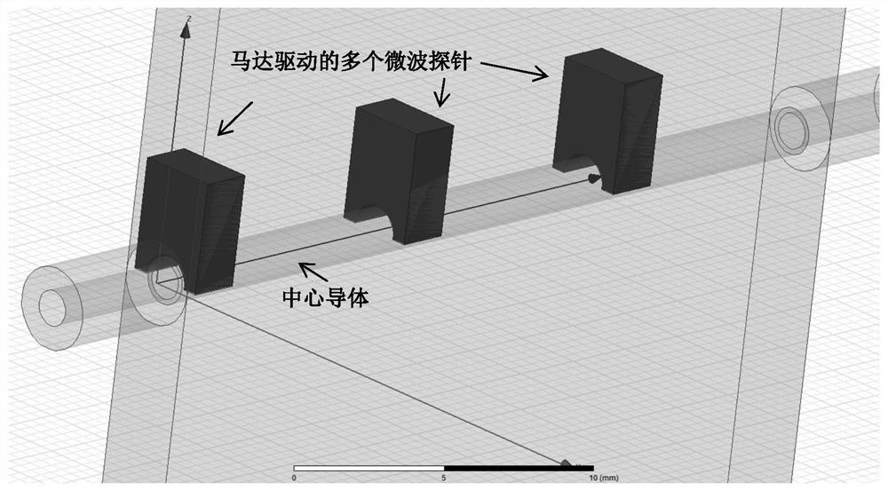
[0055] The embodiment discloses a voltage-controlled magneto-impedance converter, which includes a layer of magnetic medium layer, two sides of the magnetic medium layer are respectively connected to microwave transmission lines, and two microwaves are coupled to each other from the transmission lines. The direction of the magnetic field of the magnetic medium layer is perpendicular to the direction of the electromagnetic field of the microwave signal or rotated by an angle between 0° and 90°. The magnetic medium layer is connected to the voltage-controlled electrode through the ohmic contact layer, and the magnetic field strength or magnetic field direction of the magnetic medium layer is controlled by applying a voltage on the voltage-controlled electrode, so as to control the impedance transformation value, attenuation, phase shift, and conversion frequency point, and then realize the voltage control tuning.

[0056] The microwave transmission line is closely attached to th...

Embodiment 2

[0059] This embodiment discloses a voltage-controlled magneto-impedance transformer, which has substantially the same structure as Embodiment 1, the only difference being that the voltage-controlled magneto-impedance transformer of this embodiment is additionally designed with a metal transmission line. Metal transmission line and microwave transmission line coupling design. In some embodiments, an intermediate metal layer is designed between the magnetic medium layer and the microwave transmission line on one side, and the metal transmission line is disposed on the intermediate metal layer. In other embodiments, a groove is etched in the magnetic medium layer, and the metal transmission line is embedded in the groove. The design of the metal transmission line can further optimize the impedance transformation range, insertion loss and bandwidth.

Embodiment 3

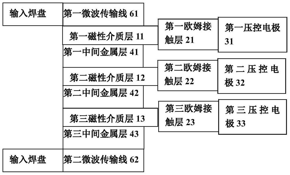
[0061] This embodiment discloses a voltage-controlled magneto-impedance converter, which includes multi-layer (at least two) magnetic medium layers and microwave transmission lines. The magnetic medium layer and the intermediate metal layer are alternately stacked layer by layer to form a multi-layer structure. Of course, it can also be Instead of alternately stacking layers one by one, for example, at least one intermediate metal layer may be provided at one or more places between the magnetic medium layer and the microwave transmission line, or between adjacent magnetic medium layers. Taking the layer-by-layer stacking structure as an example, the middle metal layer and the magnetic medium layer can be designed in equal quantities. The middle metal layer can be plate-shaped or other structures. The magnetic medium layer near the end and the metal layer of the middle piece are respectively connected to microwave transmission lines, and each microwave transmission line is resp...


PUM


Abstract

The invention discloses a voltage-controlled magnetic impedance transformer which comprises at least one magnetic dielectric layer. The magnetic dielectric layers are designed to be stacked. The magnetic dielectric layers close to the end parts are respectively connected with microwave transmission lines, and the microwave transmission lines of the two magnetic dielectric layers are coupled with each other; each magnetic dielectric layer is connected with a voltage-controlled electrode so as to change the magnetic field intensity or direction of the magnetic dielectric layer under the applied voltage; the magnetic field direction of the magnetic dielectric layer is perpendicular to the electromagnetic field direction of a microwave signal transmitted in the microwave transmission line, or the difference between the magnetic field direction of the magnetic dielectric layer and the electromagnetic field direction of the microwave signal is an angle ranging from 0 degree to 90 degrees. The voltage-controlled magnetic impedance transformer has filtering and isolating functions, and impedance conversion and frequency tuning are realized. Miniaturization design can be realized, integration is facilitated, multi-channel work can be realized, and broadband work can be realized by using a magnetic medium. The linearity can be improved, and wide-temperature and high-reliability work can be realized.

Description

technical field [0001] The invention relates to the field of microwave communication, in particular to a voltage-controlled magnetic impedance converter. Background technique [0002] There are two schemes for the impedance adjuster realized in the existing technology: one is an electronically controlled impedance adjuster based on a mechanical structure, and the other is an impedance adjuster based on adjustable discrete components such as inductors, capacitors, and resistors. The corresponding principles and structural features as follows: [0003] (1) The characteristics of the electronically controlled impedance adjuster based on the mechanical structure realized by the existing technology: [0004] (a) There is a central conductor or cavity through the signal; [0005] (b) Probes driven by mechanical motors are used to achieve impedance tuning; [0006] (c) When the motor drives the probe to move along the central conductor or cavity, the phase presented by the port ...

Claims


Application Information

Patent Timeline
Patent Type & Authority Applications(China)
IPC IPC(8): H01P5/00
CPCH01P5/00
Inventor 黄永锋殷玉喆刘伟何力
Owner 成都挚信电子技术有限责任公司
Why Eureka
Try Eureka