Air sealing body capable of automatically opening air inlets and manufacturing method thereof

An air-tight body and automatic opening technology, which is applied to hollow objects, other household utensils, and containers to prevent mechanical damage, etc. It can solve the problems that multiple air columns cannot be inflated at the same time, the air passage entrance cannot be opened, and the manufacturing process is cumbersome.

Active Publication Date: 2010-09-22
KUNSHAN AIRBAG PACKING CORP
View PDF1 Cites 22 Cited by
  • Summary
  • Abstract
  • Description
  • Claims
  • Application Information

AI Technical Summary

Problems solved by technology

However, because the check valves of this structure are independent of each other, each air column must be inflated separately, and multiple air columns cannot be inflated at the same time. Moreover, this structure makes the manufacturing process quite cumbersome. The check valve is placed at a predetermined position in the air column and then heat-sealed and bonded. Once the placement position of the check valve or the bonding position of the heat-sealing mold deviates, the check valve cannot be fixed in the air column; or It is because the inlet at the top exceeds the heat-sealing line of the heat-sealing mold, which will cause the gas to be inflated into the inflatable channel. Although the inflatable channel expands, the check valve cannot be opened with the expansion of the inflatable channel, resulting in the gas not being able to be inflated into the air column.
[0004] Another air seal structure such as Taiwan Invention Patent No. 00587049 "The installation structure of the switch valve of the seal and the manufacturing device of the seal with the switch valve", wherein the switch for air entering the seal adopts two inner membranes and one The outer membranes are bonded to each other to form the passage of the switching valve. When inflated, the sealing body expands to block the passage. This switching valve only describes how to block the air in the sealing body from leaking out, but when the air is introduced into the passage and expands, even two The outer film is pushed outward by the gas, and the switch valve will not be pulled apart with the action of the two outer films, so the two inner films of the switch valve are still attached together and the air passage inlet cannot be opened , according to its design, air cannot automatically enter the sealing body

Method used


Image

  • Air sealing body capable of automatically opening air inlets and manufacturing method thereof
  • Air sealing body capable of automatically opening air inlets and manufacturing method thereof
  • Air sealing body capable of automatically opening air inlets and manufacturing method thereof

Examples


no. 1 example

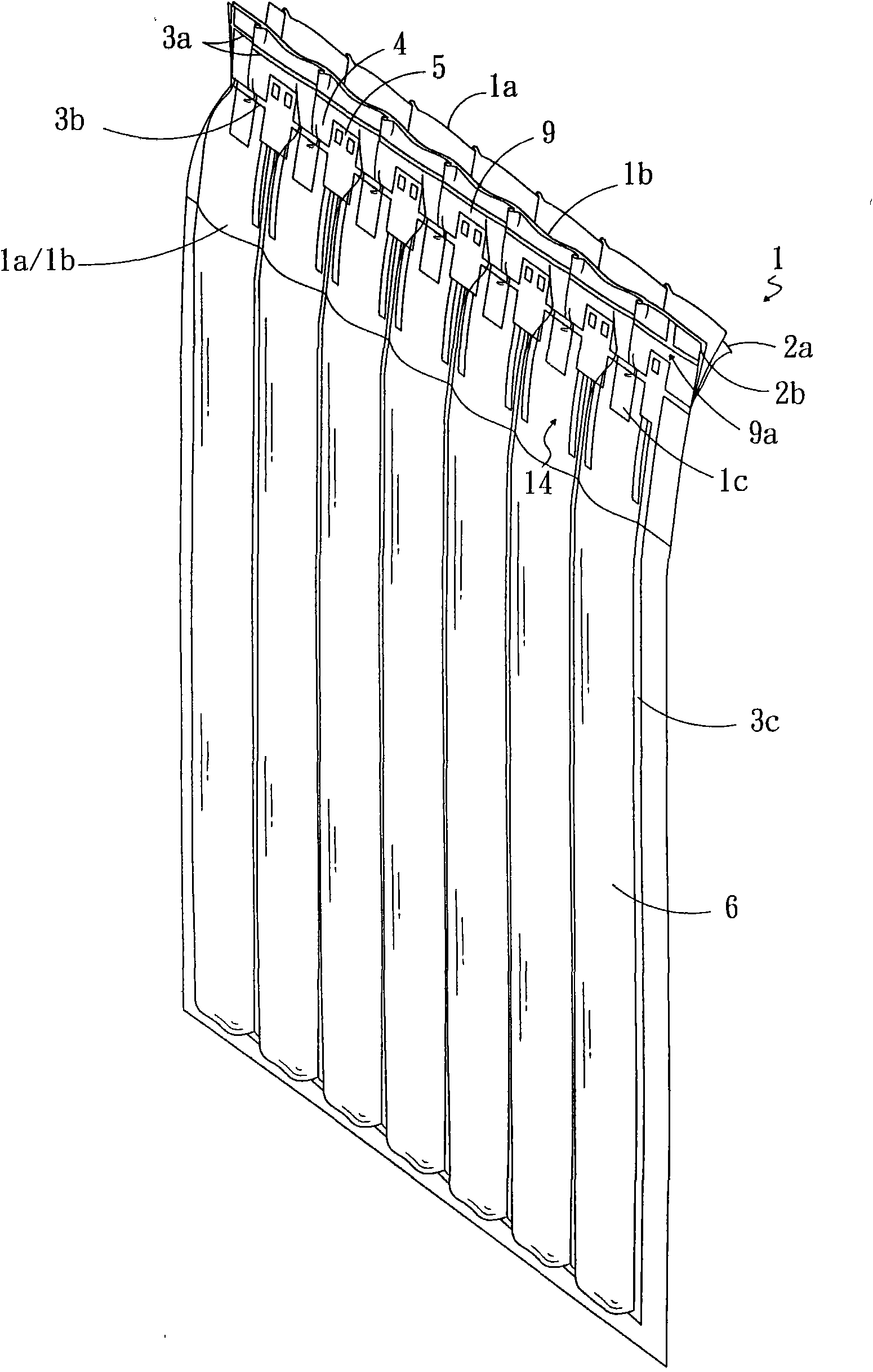
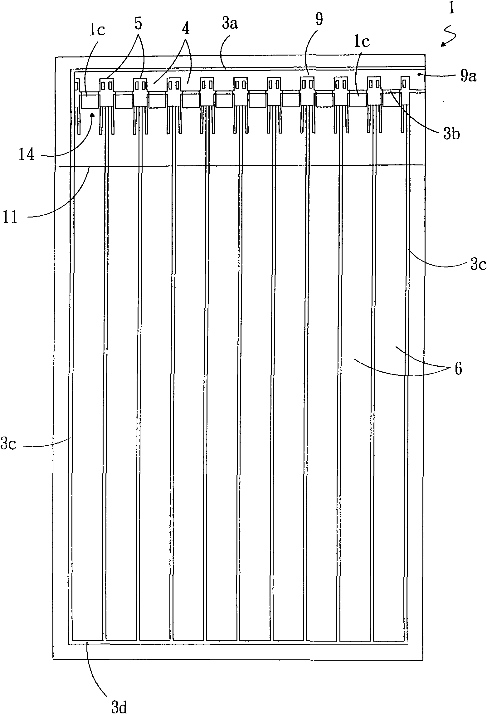
[0037] figure 1 , Figure 2A , Figure 2B , image 3 , Figure 4A , Figure 4B and Figure 5 Shown is a first embodiment of the self-opening air inlet air seal of the present invention.

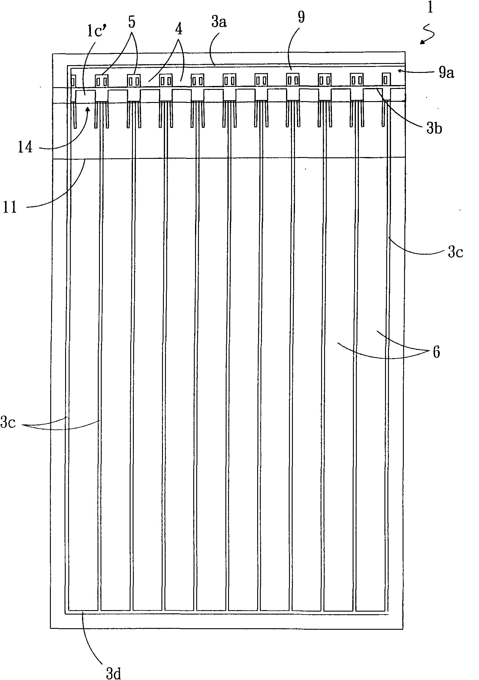
[0038] The air-tight body 1 of the present invention comprises: two outer membranes 2a and 2b superimposed up and down, two inner membranes 1a and 1b superimposed up and down, heat-resistant material 1c or 1c', an inflatable channel 9, and a plurality of air columns 6 , multiple heat-sealed blocks 5, multiple air-introducing channels 4, and the like.

[0039] The two inner membranes 1a, 1b are between the two outer membranes 2a, 2b, and the tops of the two inner membranes are lower than the tops of the two outer membranes, such as image 3 , the width of the two inner membranes is the same as that of the two outer membranes, and the length of the two inner membranes is shorter than the length of the two outer membranes, Figure 2A The middle number 11 refers to the bottom end of the t...

no. 2 example

[0049] Figure 6A and Figure 6B Shown is a second embodiment of the air seal of the present invention.

[0050] In this embodiment, the heat-sealing block 5 is composed of an air-guiding part 51 and a positioning part 52 connected to each other, and the middle heat-sealing line 3 b is located in the air-guiding part 51 . The heat-sealing block 5 can be quadrangular or elliptical as shown, and can also be circular or polygonal in various shapes, such as rectangle, square, pentagon or hexagon.

[0051] The air guide part 51 is arranged on the inflatable channel 9. When the gas entering the inflatable port 9a expands the inflatable channel 9, the air guide part 51 can guide the gas in the inflatable channel 9 into the air-inducing channel 4 and the air inlet 2e, and can Effectively increase the inflation speed and reduce the inflation time. The positioning part 52 is arranged on the air column and plays a role of positioning the entire heat-sealing block 5 .

no. 3 example

[0053] Figure 7 Shown is a third embodiment of the air seal of the present invention.

[0054] In this embodiment, the heat-sealing block 5 is composed of an air guiding part 51 and a positioning part 52 connected to each other. The positioning part 52 is elongated, and its area is larger than Figure 6A and Figure 6B The area of ​​the positioning part shown in , the area of ​​the positioning part is increased, which can play a better positioning effect on the heat-sealing block. In addition, the area of ​​the positioning portion 52 is also larger than the area of ​​the air guiding portion 51 . The heat-sealing line 3b is located in the positioning portion 52 so that the air inlet 2e is located on both sides of the positioning portion 52. Therefore, in the manufacturing process, even if the positions of the two inner films or the heat-sealing mold deviate, they do not come out of the positioning portion 52. Within the range, two pieces of inner film and two pieces of out...


PUM


Abstract

The invention provides an air sealing body capable of automatically opening air inlets. The air sealing body comprises two outer membranes, two inner membranes positioned between the two outer membranes, an air inflation channel, an air column, a middle heat-seal line for sealing two outer membranes and two inner membranes in a heating way and a plurality of heat-seal blocks, wherein a heat-resisting material is coated between two inner membranes; the middle heat-seal line separates the air inflation channel from the air column and stretches across the heat-resisting material; a plurality of air inlets are formed at the middle heat-seal line of the heat-resisting material and between two inner membranes; the air inflation channel is communicated with the air column by the air inlets; the plurality of heat-seal blocks are formed by sealing the two outer membranes and the two inner membranes in a heating way; the heat-seal blocks are positioned between adjacent two air inlets, one part of the heat-seal blocks is positioned on the air inflation channel, while the other part is positioned on the air column; the heat-seal blocks and the air inlets are alternately arranged; and the heat-seal blocks transversely shrink, and transversely extrude the two inner membranes on both sides to make the two inner membranes longitudinally pulled open so as to open the air inlets after the air inflation channel is inflated.

Description

technical field [0001] The invention relates to an air sealing body and a manufacturing method thereof, in particular to an air sealing body capable of automatically opening an air inlet and a manufacturing method thereof. Background technique [0002] The air sealing body is made of resin film, which is heat-sealed into an air column in a sealed state, and the air sealing body is provided with an inflation port for inflation. When the gas is filled into the air column through the inflation port, the air sealing body can be used as a buffer material for packaging items. [0003] The structure of the common air-tight body, such as the patent case of Japanese utility model utility model kaihei No. 5-95851 "sealed bag for fluid", is to set independent check valves on each air column, and the top of each check valve The inflow port is aligned with the heat-sealing line and bonded together. When the gas is filled into the inflatable channel, the inflatable channel is expanded an...

Claims


Application Information

Patent Timeline
Patent Type & Authority Applications(China)
IPC IPC(8): B65D81/02B29D22/02
Inventor 廖耀鑫
Owner KUNSHAN AIRBAG PACKING CORP
Why Eureka
Try Eureka