Three-way joint of fuel evaporation and emission control pipeline

An evaporative emission and pipeline control technology, applied in the direction of pipes/pipe joints/fittings, branch pipelines, pipes, etc., to achieve the effect of standard layout, cost reduction, and fewer pipe clamps

Inactive Publication Date: 2010-09-22
CHONGQING LONCIN MOTOR
View PDF6 Cites 0 Cited by
  • Summary
  • Abstract
  • Description
  • Claims
  • Application Information

AI Technical Summary

Problems solved by technology

[0005] The purpose of the present invention is to provide a fuel evaporative emission control pipeline tee joint that does not easily cause air blockage in the pipeline

Method used


Image

  • Three-way joint of fuel evaporation and emission control pipeline
  • Three-way joint of fuel evaporation and emission control pipeline
  • Three-way joint of fuel evaporation and emission control pipeline

Examples


Embodiment Construction

[0018] The present invention will be further described below in conjunction with drawings and embodiments.

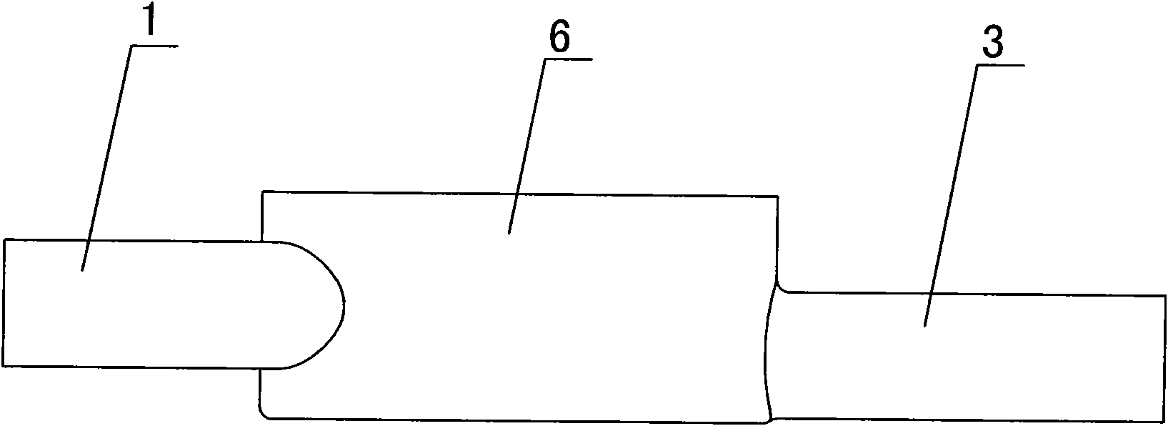
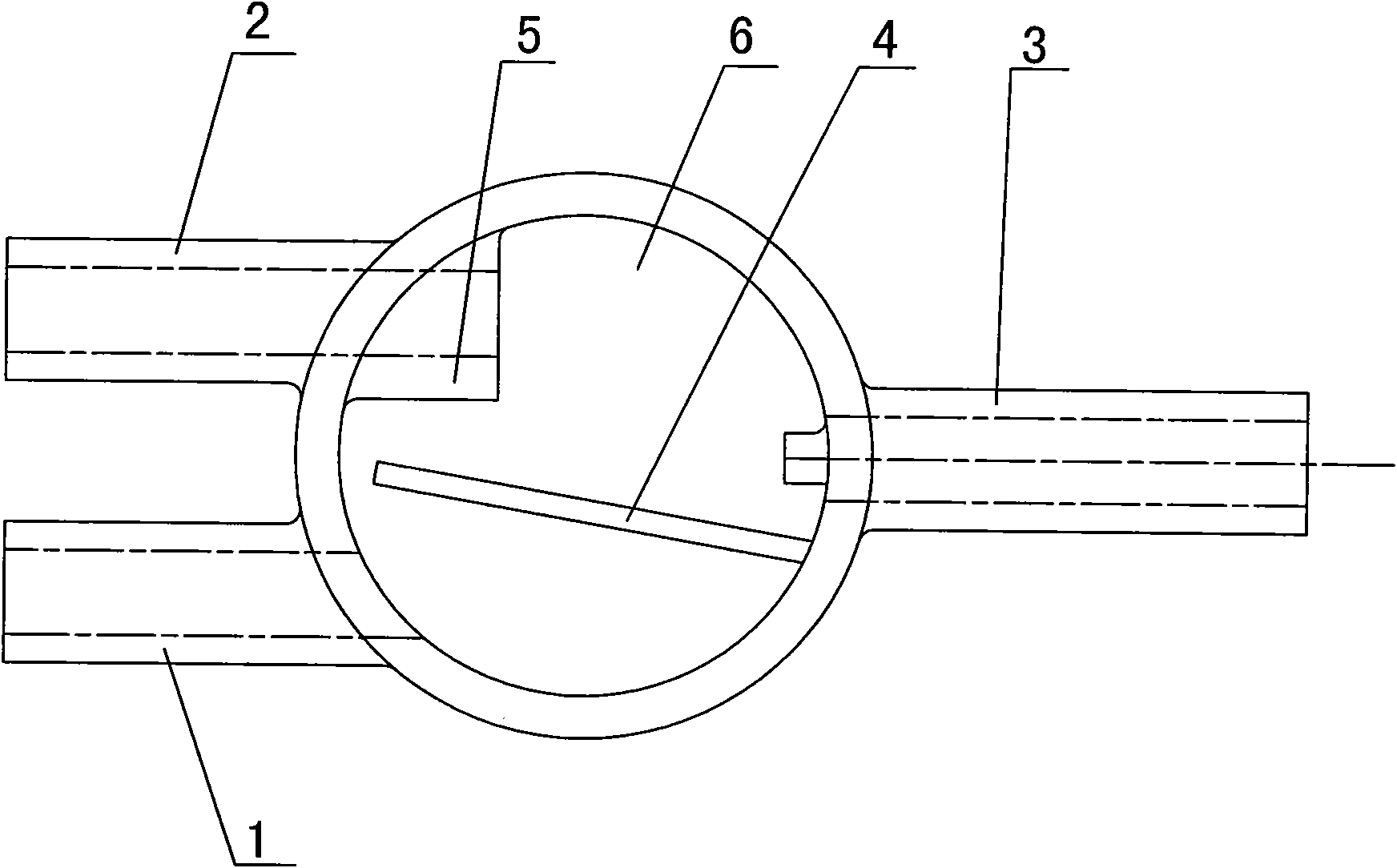
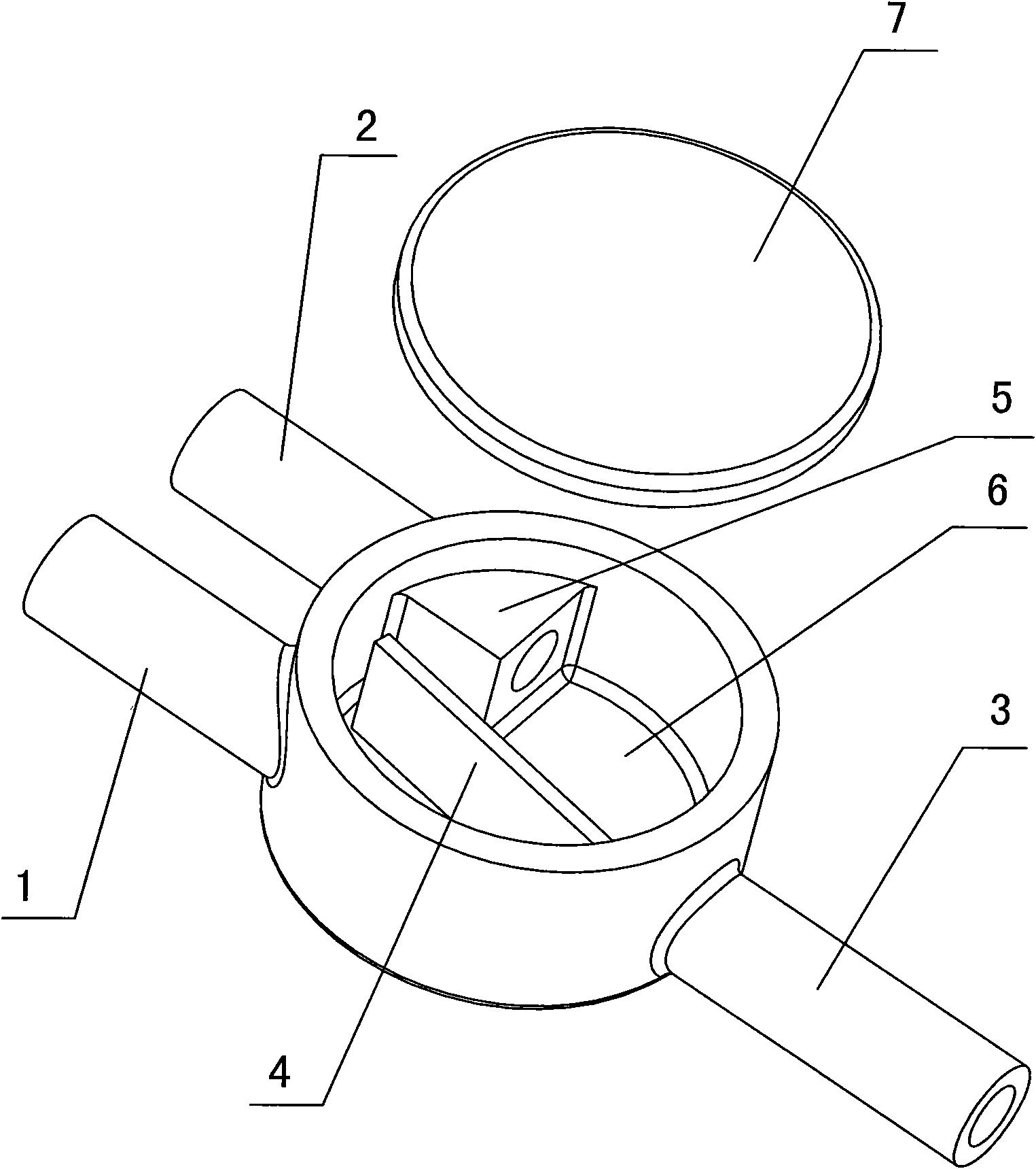
[0019] like Figure 1 to Figure 4 As shown, the tee joint of the fuel evaporative emission control pipeline has a first branch pipe 1, a second branch pipe 2 and a third branch pipe 3 that communicate with each other, and the orientation of the first branch pipe 1, the second branch pipe 2 and the third branch pipe 3 are opposite , the three branch pipes meet in the cylindrical cavity 6, and a baffle plate 4 is arranged in the cylindrical cavity 6. The baffle plate 4 makes the gap between the first branch pipe 1 and the second branch pipe 2, and between the first branch pipe 1 and the third branch pipe 3 To achieve a circuitous connection between. When in use, the first branch pipe 1 is used to connect the one-way air valve, the second branch pipe 2 is connected with the fuel tank, the third branch pipe 3 is connected with the carbon canister, and the baffle plate 4 in...


PUM


Abstract

The invention provides a three-way joint of a fuel evaporation and emission control pipeline, which is provided with a first branch pipe, a second branch pipe and a third branch pipe which are mutually communicated, wherein the orientations of the first branch pipe, the second branch pipe and the third branch pipe are opposite. The three-way joint is characterized in that three branch pipes are met at a columnar cavity in which a baffle is arranged, the baffle causes the first branch pipe to be circuitously communicated with the second branch pipe and causes the first branch pipe to be circuitously communicated with the third branch pipe, and the connection position of the third branch pipe on the columnar cavity is lower than those of the first branch pipe and the second branch pipe. The technical scheme of the invention can effectively prevent air blockage caused by gathering of fuel near the three way joint; meanwhile, the arrangement of the fuel evaporation and emission control pipeline is more normalized and compact, less pipe clamps are needed, and cost is lowered.

Description

technical field [0001] The invention relates to a pipeline tee joint, in particular to a fuel oil evaporation emission control pipeline tee joint. Background technique [0002] The existing gasoline vehicle fuel evaporation pollutant emission control system mainly includes a carbon tank, an intake pipe, an exhaust pipe and a negative pressure pipe. The intake pipe is connected between the carbon tank and the fuel tank, and the exhaust pipe and the negative pressure pipe are connected in the Between the canister and the carburetor, the intake pipe is usually equipped with a dump valve to prevent the gasoline in the fuel tank from entering the canister when the vehicle is dumped. On motorcycles, the carbon canister is fixedly installed on the frame, and the intake pipe, exhaust pipe and negative pressure pipe are generally flexible pipes. Since there are many components installed on the frame and the structure is compact, it is difficult to ensure that the above-mentioned flex...

Claims


Application Information

Patent Timeline
Patent Type & Authority Applications(China)
IPC IPC(8): F02M37/20F02M25/08F16L41/02
Inventor 张俊戴军昌
Owner CHONGQING LONCIN MOTOR
Why Eureka
Try Eureka