Generating method of finite element mesh in thin-wall curved surface structure

A technology for surface structure and mesh generation, which is used in special data processing applications, instruments, electrical digital data processing, etc.

Inactive Publication Date: 2010-09-22
NANTONG HENGDA MACHINERY MFG +1
View PDF0 Cites 18 Cited by
  • Summary
  • Abstract
  • Description
  • Claims
  • Application Information

AI Technical Summary

Problems solved by technology

However, for thin-walled surface structures with holes, due to the needs of optimal design, the position and shape of the holes are generally variable parameters, and the geometric model is more complicated. At this time, only the precise establishment of the geometric model itself is difficult, so it is not easy to use Solid Modeling Method to Generate Finite Element Mesh
The direct generation method allows the user to have complete control over the numb

Method used


Image

  • Generating method of finite element mesh in thin-wall curved surface structure
  • Generating method of finite element mesh in thin-wall curved surface structure
  • Generating method of finite element mesh in thin-wall curved surface structure

Examples


Embodiment 1

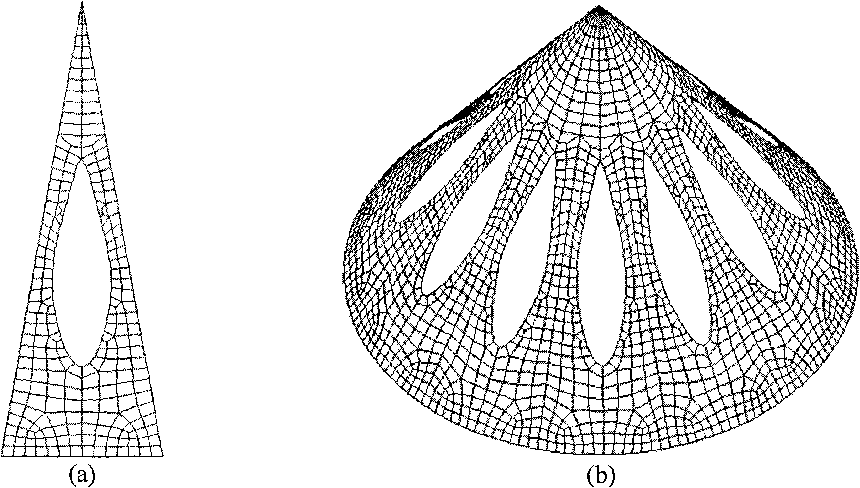
[0059] Example 1: Thin-walled conical surface structure with holes.

[0060] There are 12 cyclically symmetric holes on the thin-walled conical surface structure. The basic parameters are shown in Table 1.

[0061] Table 1

[0062]

[0063]

[0064] (a) According to the geometric characteristics of the conic surface structure, establish the parameter equation of its one-twelfth unit cell structure:

[0065] x = 200 ( 1 - t ′ ) cos ( 1.4999 s ′ ) y = 200 ( 1 - t ′ ) sin ( 1.4999 s ′ ) z = 300 t ′ , 0 ≤ s ′ ≤ 0.3491,0 ≤ t ′ ≤ 1 . - - - ( 14 )

[0066] Thus, the s-t parameter plane is established, and the rectangular mapping domain on the s-t plane with a width of 0.3491 and a length of 1.

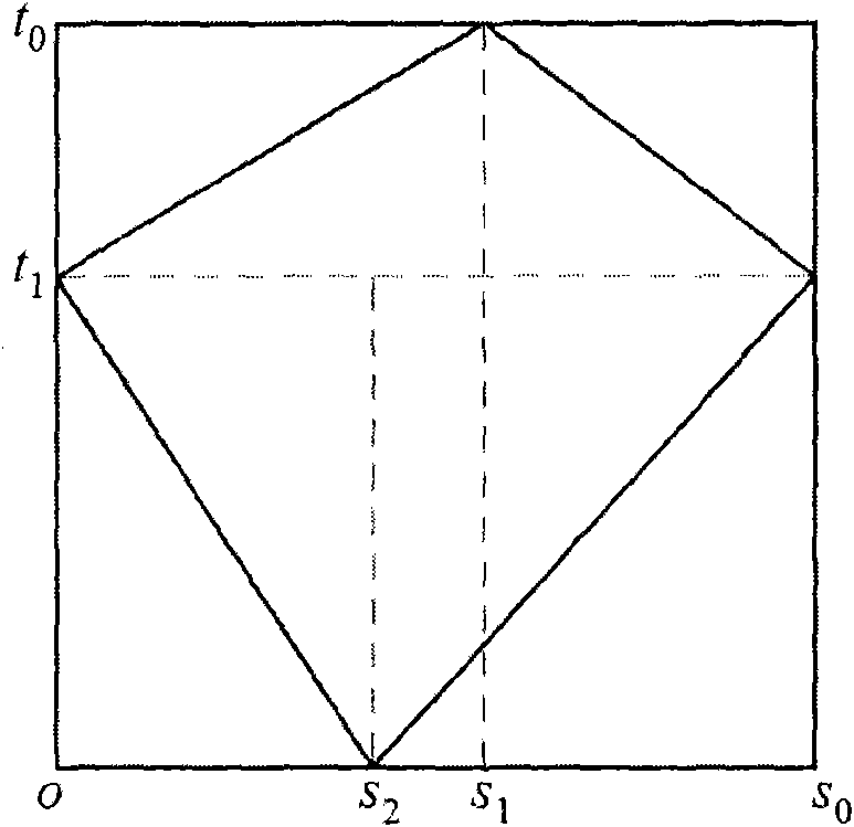
[0067] (b) The one-twelfth unit cell structure of the thin-walled conical surface is a three-sided surface structure, so the actual plane mapping doma...

Embodiment 2

[0081] Example 2: Thin-walled hemispherical surface structure with holes.

[0082] There are 4 cyclically symmetrical holes on the thin-walled hemispherical surface structure. The basic parameters are shown in Table 2.

[0083] Table 2

[0084]

[0085] (a) According to the structural characteristics of the cyclic symmetry of the thin-walled hemispheric surface structure with holes, the parameter equation of the quarter cell structure is established:

[0086] x = 300 cos 0.5 πt ′ cos 0.5 πs ′ y = 300 cos 0.5 πt ′ sin 0.5 πs ′ z = 300 sin 0.5 πt ′ , 0 ≤ s ′ , t ′ ≤ 1 . - - - ( 19 )

[0087] Thus, the s-t parameter plane is established, and the rectangular mapping domain with width 1 and length 1 on the s-t plane is established.

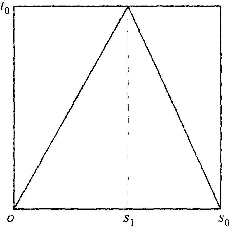
[0088] (b) The thin-walled hemispherical surface unit cell structure with a hole is a three-sided surface structure, so the actual plan...

Embodiment 3

[0102] Example 3: Thin-walled cylindrical curved sheet structure with holes (free mesh).

[0103] There is a hole in the structure of a thin-walled cylindrical surface sheet, and its basic parameters are shown in Table 3.

[0104] table 3

[0105]

[0106]

[0107] (a) Establish a parameterized equation for the structure of the thin-walled cylindrical surface sheet in space:

[0108] x = 400 cos ( 2.5 s ′ ) y = 400 sin ( 2.5 s ′ ) z = 1000 t ′ , 0 ≤ s ′ , t ′ ≤ 1 . - - - ( twenty four )

[0109] Thus, the s-t parameter plane is established, and the rectangular mapping domain with width 1 and length 1 on the s-t plane is established.

[0110] (b) The cylindrical surface patch has a four-sided surface structure, and the actual planar mapping domain is selected as a rectangle.

[0111] (c) At this time, the rectangular mapping domain is the actual mapping domain of the cylind...


PUM


Abstract

The invention discloses a generating method of a finite element mesh in a thin-wall curved surface structure, aiming to solve the technical problem of great equivalent stress of a traditional design method of a finite element model in a perforated thin-wall conical curved surface structure. The technical scheme comprises the following steps of: firstly, generating a plane finite element mesh on a parameter plane by adopting a solid modeling method; then, generating network nodes in a space thin-wall curved surface structure through a parametric mapping relation by adopting a direct generating method; and generating a finite element mesh in the space thin-wall curved surface structure by utilizing corresponding unit topology information on the parameter plane. Compared with the prior art, the maximum equivalent stress of the finite element model in the perforated thin-wall conical curved surface structure in the same size is greatly reduced.

Description

Technical field [0001] The invention relates to a finite element mesh generation method, in particular to a finite element mesh generation method for a thin-walled curved surface structure. Background technique [0002] The document "Release 11.0 Documentation for ANSYS.ANSYS Incorporated, 2005." discloses two finite element mesh generation methods: a solid modeling generation method and a direct generation method. When using the solid modeling generation method, firstly, a geometric model needs to be established to describe the geometric boundary of the model, and then the size and shape of the element are controlled. Finally, the ANSYS program automatically generates all the nodes and elements of the finite element mesh. When using the direct generation method, it is necessary to first determine the location of each node, then generate all nodes of the finite element mesh, and then determine the size, shape and connection form of each element to generate all elements of the fin...

Claims


Application Information

Patent Timeline
IPC IPC(8): G06F17/50
Inventor 张卫红王丹杨军刚王振培
Owner NANTONG HENGDA MACHINERY MFG
Why Eureka
Try Eureka