
Metal spring leaf

A metal reed and blade technology, applied in the field of electronic products, can solve the problems of bump deformation, improper force direction and deformation of the metal reed, and achieve the effect of increasing the force direction, high force strength and not easy to damage.

Active Publication Date: 2010-09-22
ZTE CORP
View PDF5 Cites 15 Cited by
  • Summary
  • Abstract
  • Description
  • Claims
  • Application Information

AI Technical Summary

Problems solved by technology

The force direction range of this kind of metal reed is relatively small, and the improper force direction of the metal reed often occurs in the application, resulting in deformation
In addition, there are bumps and deformations, and sometimes the PCB pads are pulled up due to excessive force, resulting in the scrapping of the PCB

Method used


Image

  • Metal spring leaf
  • Metal spring leaf
  • Metal spring leaf

Examples


Embodiment Construction

[0017] The invention provides a metal reed, which can increase the force direction and range of the spring, and can be applied in some environments requiring force in multiple directions in electronic products.

[0018] The metal reed of the present invention is fixed on the PCB board or other electronic devices, and the PCB board or other electronic devices is provided with a hole, the metal reed is arranged in the hole, and passes through the fixed end fixed on the PCB board or other electronic devices.

[0019] The metal reed of the present invention will be described in detail below in conjunction with the accompanying drawings and specific embodiments.

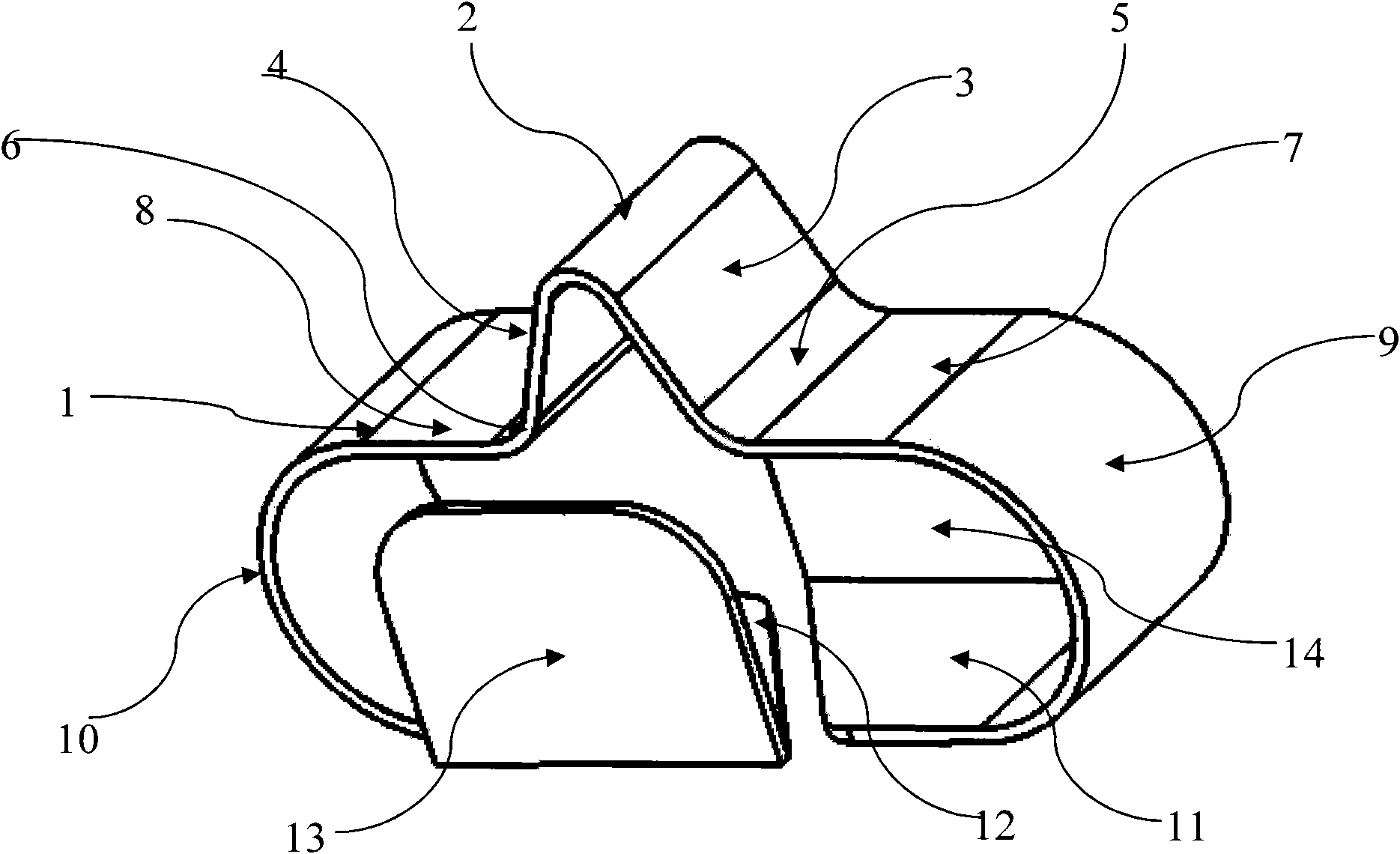
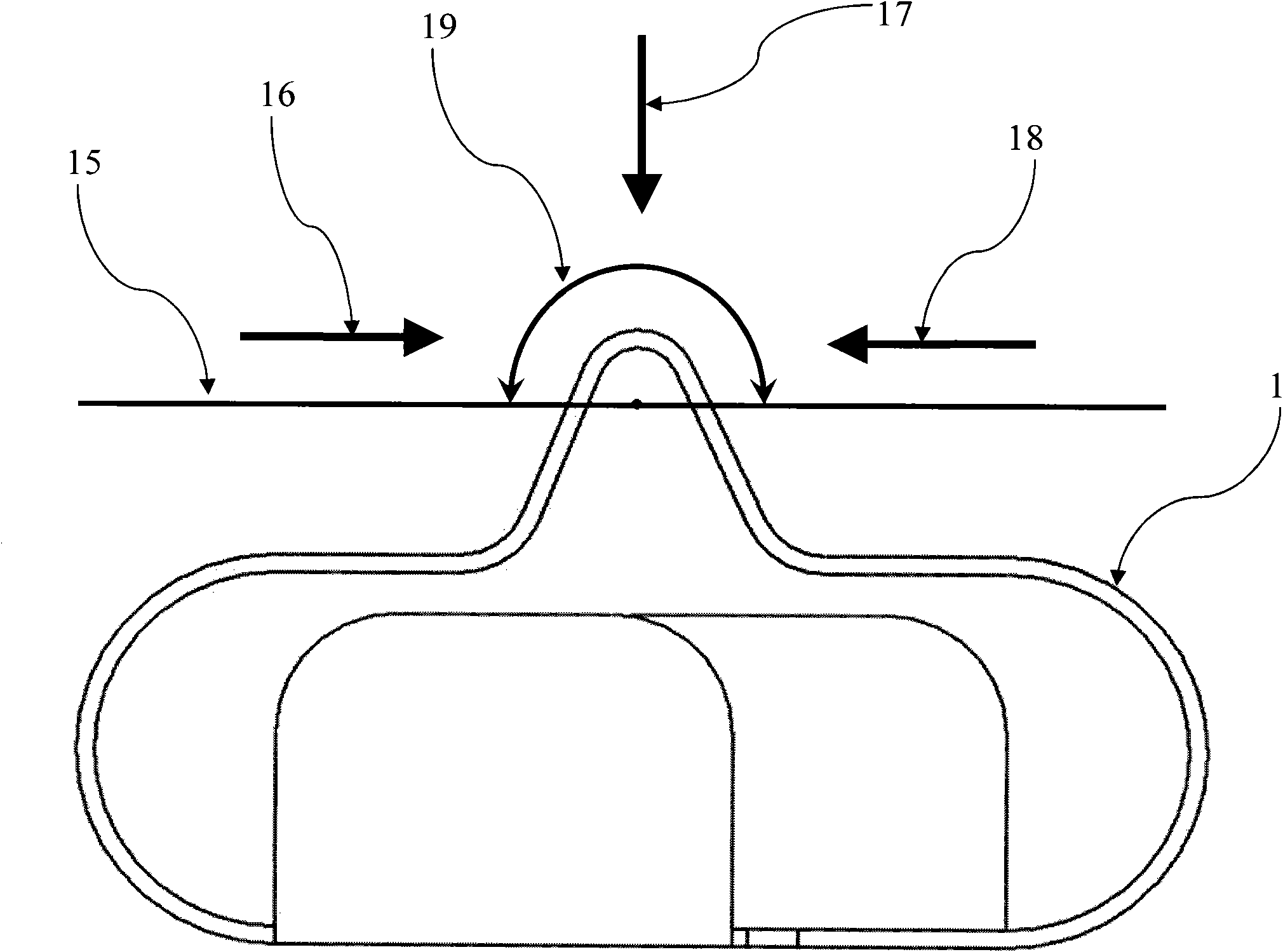
[0020] like figure 1 As shown, the metal reed 1 includes a contact portion, bending portions respectively extending from two bottom ends of the contact portion, and fixing portions respectively extending from the bending portions. The contact portion is in the shape of a saddle, and includes a contact end 2 and two firs...


PUM


Abstract

The invention discloses a metal spring leaf, which comprises a contact part, bending parts extending from two bottom ends of the contact part respectively, and fixing parts extending from the bending parts respectively, wherein the contact part is provided with a contact end contacting a conducting device; the bending parts and the contact part are elastic; and the fixing parts are used for fixing the metal spring leaf on a PCB board or other electronic devices. Relative to a relevant technique, because the two ends of the contact part are provided with the bending parts by extending to increase a stressed direction and make the stress strength at a contact end stronger, the metal spring leaf is difficult to damage.

Description

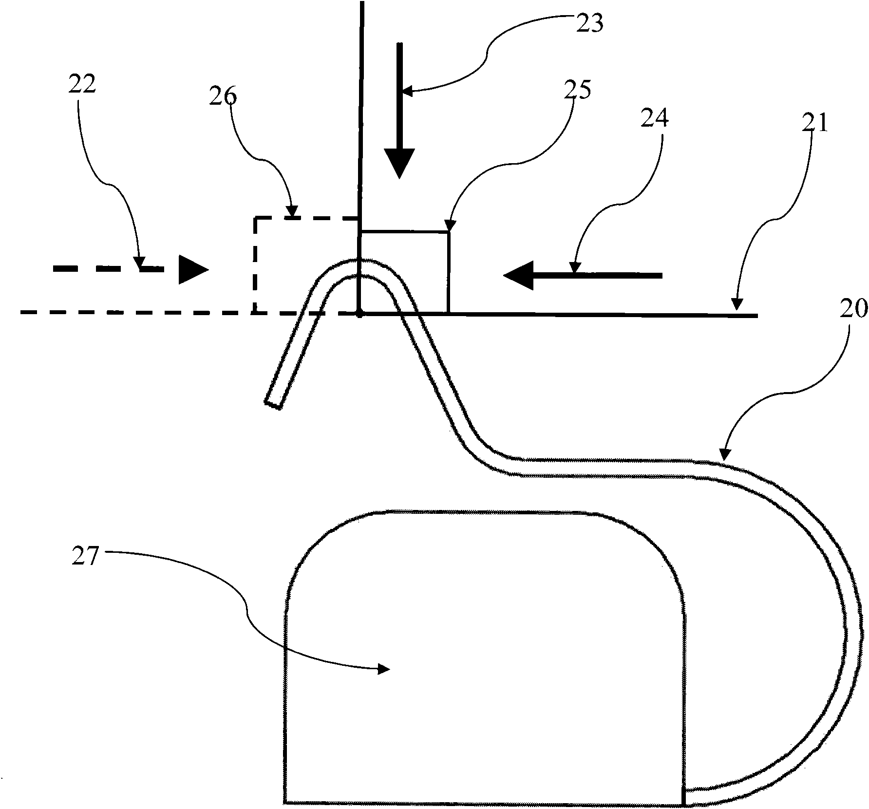
technical field [0001] The invention relates to the field of electronic products, and more specifically, relates to a metal reed used in electronic products. Background technique [0002] Metal reeds are often used in electronic products such as mobile phones and data cards for the connection and conduction of antenna radio frequency signals, the ground connection of PCB (Printed circuit board, printed circuit board) components, and electromagnetic shielding. [0003] The current application method is: curl one end of the metal reed, fix the other end of the metal reed on the surface of the PCB board by manual fixing or patching, and place the structure body completely on the surface of the PCB board. The force direction range of this kind of metal reed is relatively small, and it often happens that the force direction of the metal reed is improper in application, resulting in deformation. In addition, there are also cases of bumping and deformation, and sometimes even the ...

Claims


Application Information

Patent Timeline
IPC IPC(8): H01R12/30H01R12/36H01R13/24H01R13/60H01R12/57
Inventor 孙盈军任东江张磊
Owner ZTE CORP
Learn More