Single-antenna remote radio unit

A technology of remote radio unit and single antenna, which is applied in electrical components, wireless communication, radio relay system, etc., can solve the problems of large power loss and small transmission capacity, reduce power loss and equipment volume, increase Effects of transmission capacity, improvement of coverage capability and coverage efficiency

Active Publication Date: 2010-09-22
北京万海云科技有限公司
View PDF4 Cites 42 Cited by
  • Summary
  • Abstract
  • Description
  • Claims
  • Application Information

AI Technical Summary

Problems solved by technology

In short, the current single-antenna RRU has a small transmission capacity and a large power loss

Method used


Image

  • Single-antenna remote radio unit
  • Single-antenna remote radio unit
  • Single-antenna remote radio unit

Examples


Embodiment Construction

[0061] In order to make the object, technical solution and advantages of the present invention clearer, the present invention will be described in detail below in conjunction with the accompanying drawings and specific embodiments.
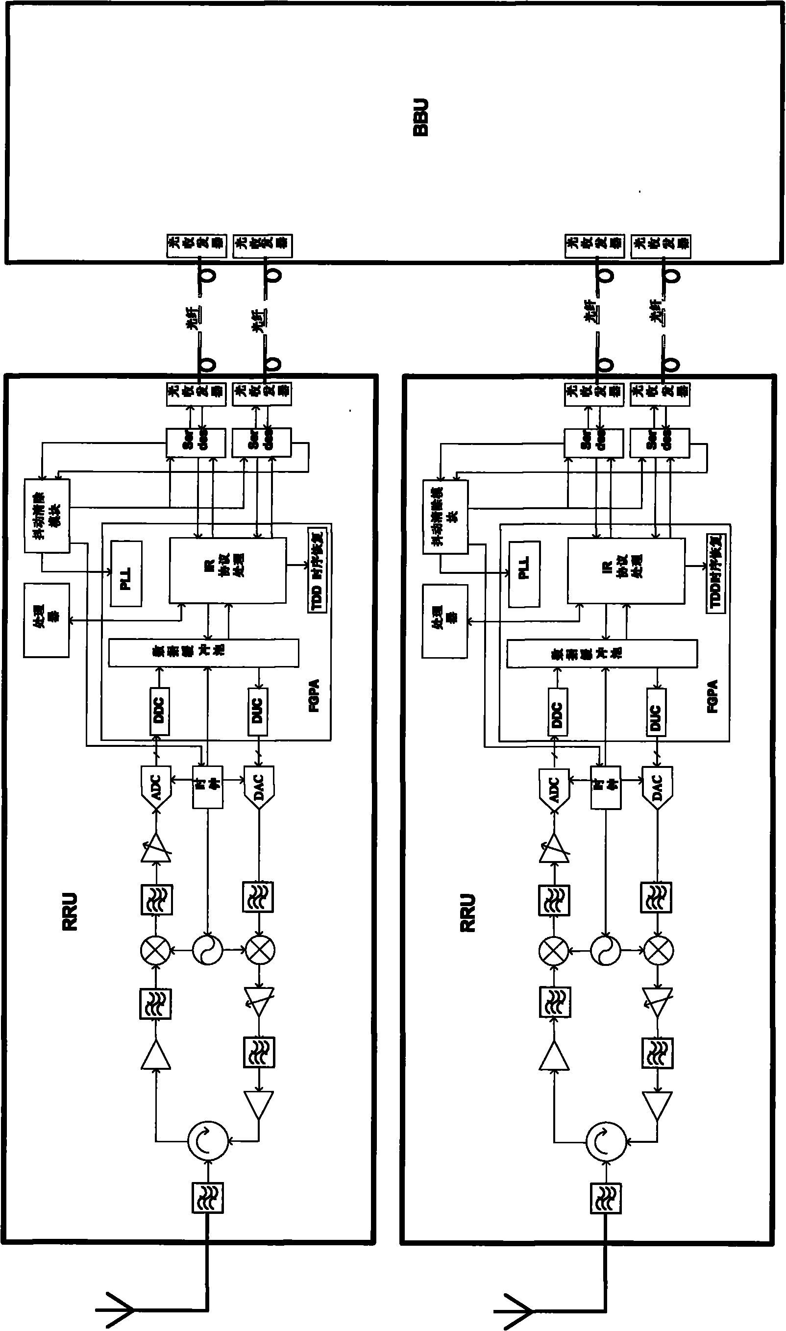
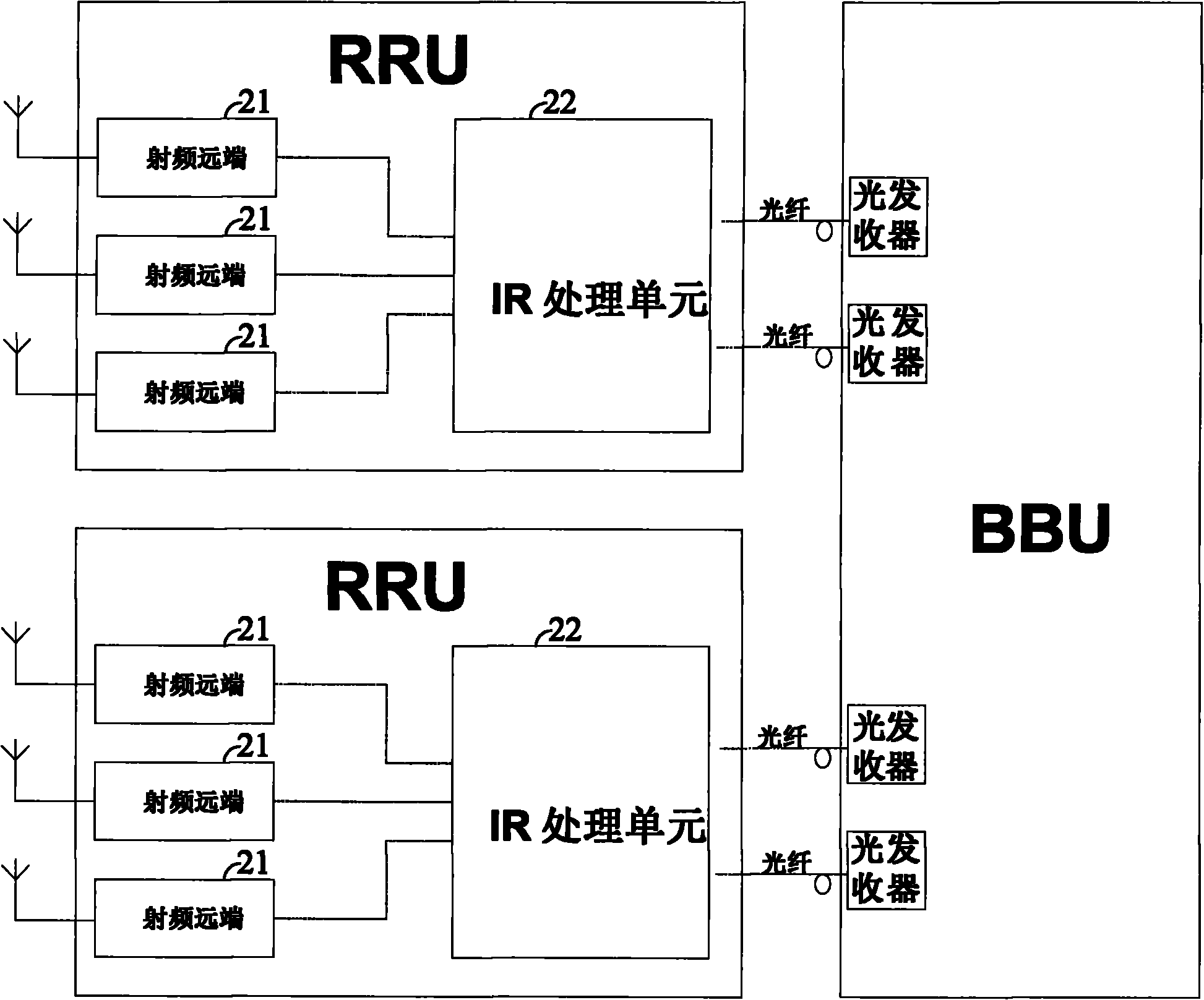
[0062] The basic idea of ​​the present invention is that each single-antenna RRU consists of two independent devices, including one or more radio frequency remote ends and an IR processing unit. Wherein, multiple radio frequency remote ends are located in an independent device, and the device is placed on the side of the antenna, and each radio frequency remote end is connected to an antenna. The IR processing unit is located in another separate device, which is located indoors. The above two devices are connected through a bundled cable, and the above two devices jointly form an RRU.

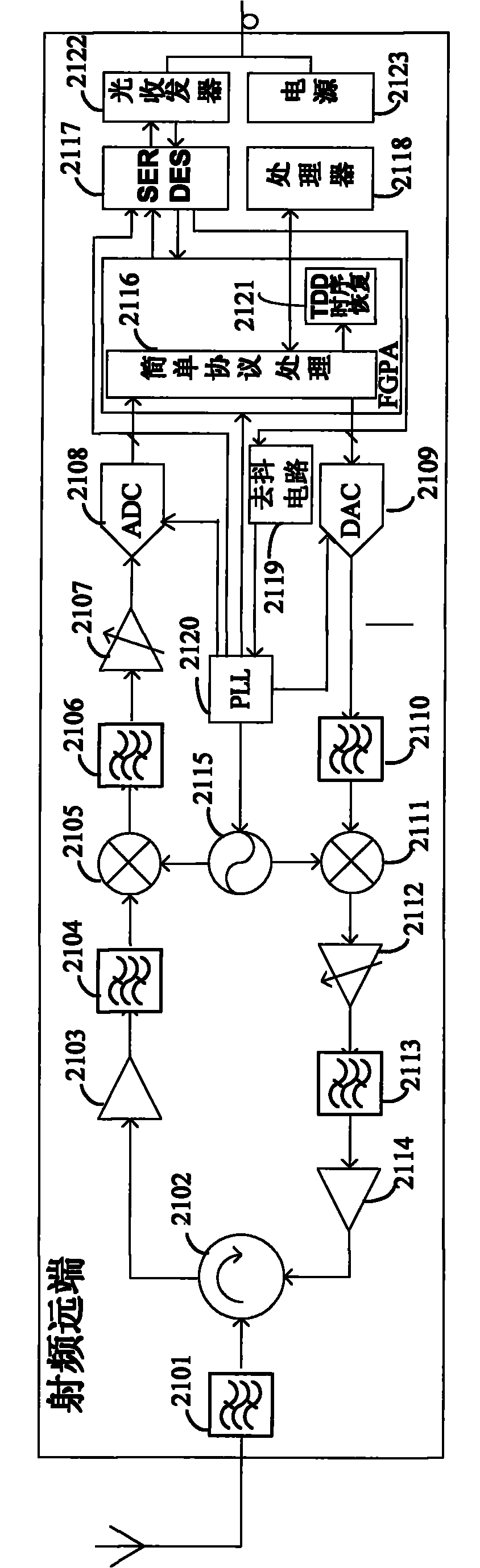
[0063] figure 2 It is a schematic structural diagram of a single-antenna RRU according to an embodiment of the present invention. Such as figure 2 As shown, ...


PUM


Abstract

The invention discloses a single-antenna RRU (remote radio unit) comprising one or a plurality of radio-frequency far ends and an IR processing unit, wherein each radio-frequency far end is connected with an antenna, a received uplink analog radio-frequency signal is processed into an uplink digital intermediate-frequency signal, the uplink digital intermediate-frequency signal is transmitted to the IR processing unit, a downlink digital intermediate-frequency signal from the IR processing unit is received and is processed into a downlink analog radio-frequency signal, and the downlink analogradio-frequency signal is transmitted to the antenna. Simple protocol transmission is adopted between the radio-frequency far ends and the IR processing unit. The IR processing unit processes the uplink digital intermediate-frequency signal from each radio-frequency far end into an uplink digital baseband signal, the uplink digital baseband signal is transmitted to a BBU, a downlink digital baseband signal from the BBU is processed into a downlink digital intermediate-frequency signal, and the downlink digital intermediate-frequency signal is transmitted by selecting one of all the radio-frequency far ends. By adopting the single-antenna RRU, a plurality of radio-frequency far ends can be adopted to carry out coverage, so that the transmission capacity of the RRU can be expanded.

Description

technical field [0001] The present invention relates to mobile communication technology, in particular to a single-antenna remote radio unit (RRU) used in Time Division Synchronous Code Division Multiple Access (TD-SCDMA) system and Time Division Long Term Evolution (TD-LTE) system. Background technique [0002] At present, in the TD-SCDMA system and the TD-LTE system, the RRU and the baseband processing unit (BBU) are commonly used to form a distributed base station architecture. figure 1 It is a structural schematic diagram of an existing single-antenna RRU. Such as figure 1 As shown, one BBU is connected to one or more RRUs, figure 1 Taking one BBU connected to two RRUs as an example, the BBU and the RRU are connected through an optical fiber. Correspondingly, both the BBU and the RRU include an optical transceiver connected to the optical fiber. One RRU is connected to one antenna, and the equipment of the RRU is located indoors, and is connected to the antenna throug...

Claims


Application Information

Patent Timeline
IPC IPC(8): H04W88/08H04B7/15
Inventor 苗英葛芷斌岳士丰
Owner 北京万海云科技有限公司
Why Eureka
Try Eureka