Universal rolling technology for rails

A universal rolling mill and universal technology, applied in the direction of metal rolling, etc., can solve the problems of good processing quality, uneven stress on rail-shaped rolled pieces, poor processing quality, etc., and achieve good processing quality, uniform force, and good symmetry Effect

Active Publication Date: 2010-09-29
PANGANG GROUP VANADIUM TITANIUM & RESOURCES +1
View PDF7 Cites 20 Cited by
  • Summary
  • Abstract
  • Description
  • Claims
  • Application Information

AI Technical Summary

Problems solved by technology

[0003] 1. During the rolling process of the universal rolling mill, since the head of the rail-shaped rolling piece in the pass is suspended, the rail-shaped rolling piece may be twisted in the pass, and the twisted rail-shaped rolling piece is rolled Uneven stress during the process leads to poor symmetry of the final finished rail, and the symmetrical difference between the upper and lower legs reaches 2-3 mm;
[0004] 2. The rail-shaped rolled piece after twisting may also cause the upper and lower horizontal rolls of the universal rolling mill to rub in their respective axial directions, so that one side of the upper and lower horizontal rolls has a large force and the other side has a small force, which leads to rail-shaped The force on the abdominal cavi

Method used


Image

  • Universal rolling technology for rails
  • Universal rolling technology for rails
  • Universal rolling technology for rails

Examples


Embodiment 1

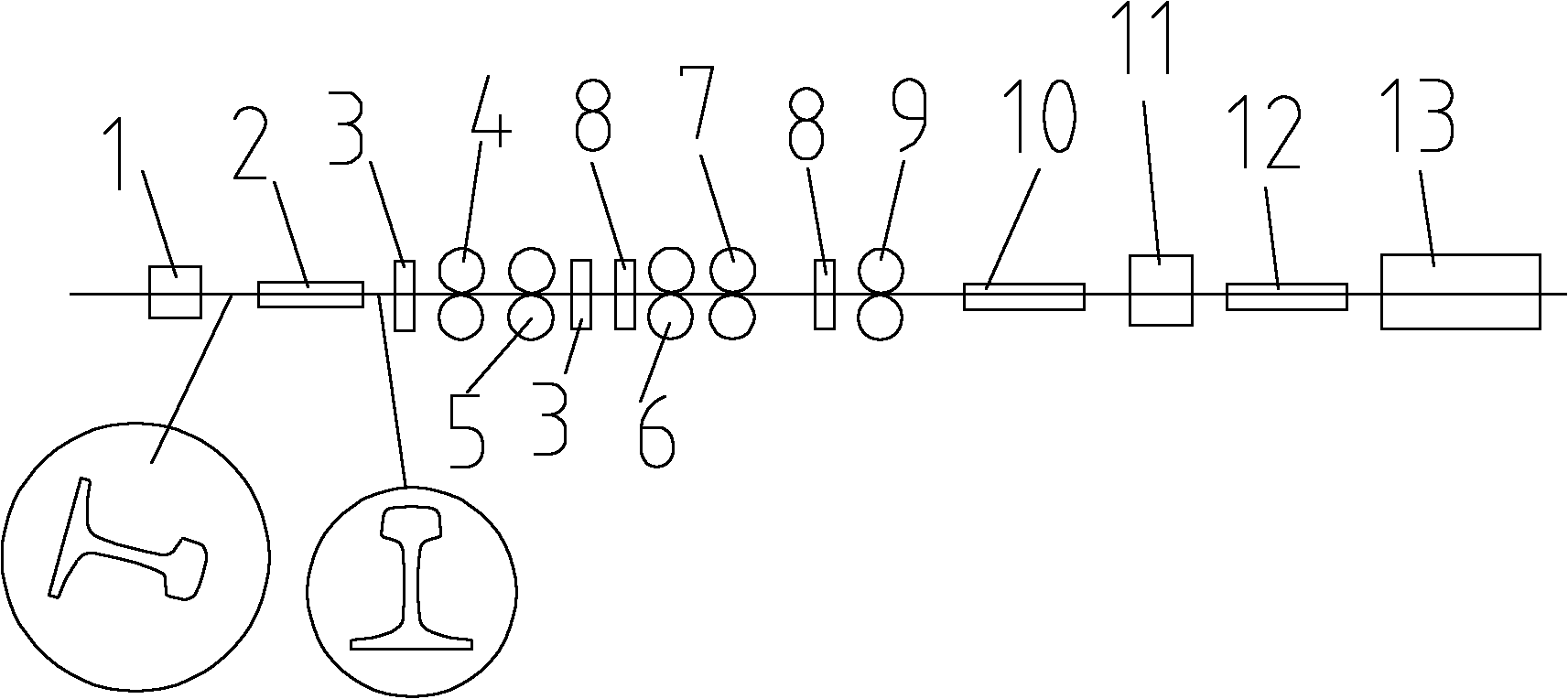
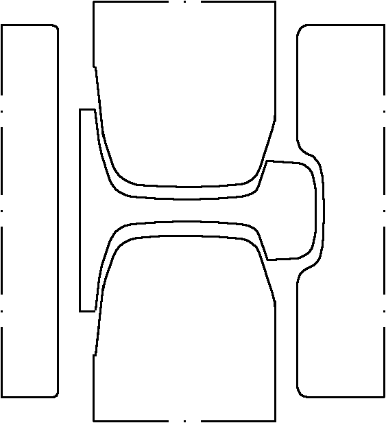
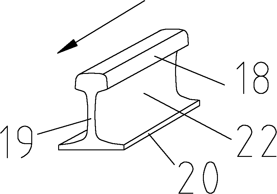
[0039] Depend on figure 1 , Figure 5 and Figure 7 As shown, after the rail-shaped rolling piece is rolled out from the pilot hole of BD area 1, before entering the universal area, it is turned over by the first turning device 2, and the waist 19 of the rail-shaped rolling piece becomes vertical, and the rail-shaped rolling piece The head 18 is positioned above the legs 20; then the overturned rail-shaped rolled piece enters the universal zone to carry out intermediate rolling and finish rolling through the vertical universal rolling mill and the vertical edger. During the rolling process in the universal zone, The waist 19 of the rail-shaped rolled piece is in a vertical state, the abdominal cavity 22 of the rail-shaped rolled piece is rolled by the left and right vertical rolls of the vertical universal rolling mill, and the head 18 of the rail-shaped rolled piece is supported by the left and right vertical rolls of the vertical universal rolling mill; Then the rail-shap...

Embodiment 2

[0041] Depend on figure 1 , Figure 5 and Figure 7 As shown, after the rail-shaped rolling piece is rolled out from the pilot hole of BD area 1, before entering the universal area, it is turned over by the first turning device 2, and the waist 19 of the rail-shaped rolling piece becomes vertical, and the rail-shaped rolling piece The head 18 is positioned above the legs 20; then the overturned rail-shaped rolled piece enters the universal zone to carry out intermediate rolling and finish rolling through the vertical universal rolling mill and the vertical edger. During the rolling process in the universal zone, The waist 19 of the rail-shaped rolled piece is in a vertical state, the abdominal cavity 22 of the rail-shaped rolled piece is rolled by the left and right vertical rolls of the vertical universal rolling mill, and the head 18 of the rail-shaped rolled piece is supported by the left and right vertical rolls of the vertical universal rolling mill; Before the rail-sh...

Embodiment 3

[0043] On the basis of Embodiment 1 or Embodiment 2, the pass pattern of the vertical universal rolling mill used for intermediate rolling in the universal area is formed by the upper and lower horizontal rolls and the left and right vertical rolls, and the vertical universal rolling mill used for intermediate rolling The ratio of the linear velocity of the lower horizontal roller to the linear velocity of the upper horizontal roller is 1.01-1.03. The ratio of the linear velocity of the lower horizontal roller to the linear velocity of the upper horizontal roller can be 1.01, 1.015, 1.02 or 1.03 and so on. When the roll diameters of the upper horizontal roll and the lower horizontal roll are the same, the rotational speed of the lower horizontal roll can be greater than that of the upper horizontal roll, so that the ratio of the linear speed of the lower horizontal roll to that of the upper horizontal roll is 1.01-1.03 Certainly, under the same situation of rotating speed, als...


PUM


Abstract

The invention discloses a universal rolling technology for rails, which can prevent the head of a rail-shaped rolled piece from being suspended in a rolling process. The technology comprises the following steps: a billet is cogged in a BD region to form a rail-shaped rolled piece; after the rail-shaped rolled piece is rolled out of a pilot hole of the BD region and before the rail-shaped rolled piece enters a universal region, the waist of the rail-shaped rolled piece is changed into a vertical state through the overturning of a turnover device; then, the rail-shaped rolled piece is conveyed into the universal region for intermediate rolling and fine rolling through a vertical universal mill and a vertical edging mill; in the rolling process of the universal region, the waist of the rail-shaped rolled piece is in the vertical state, the abdominal cavity of the rail-shaped rolled piece is rolled through a left vertical roller and a right vertical roller of the vertical universal mill, and the head of the rail-shaped rolled piece is supported by the left vertical roller and the right vertical roller of the vertical universal mill; and the rail-shaped rolled piece is conveyed into a rail printer for printing, and the rail-shaped rolled piece after printing is conveyed into a cooling bed for cooling. By adopting the technology, the final finished rail has the advantages that the head is fully filled, the abdominal cavity has better processing quality, and the working tread is better filled and has better symmetry.

Description

technical field [0001] The invention relates to a rolling process of a steel rail, in particular to a universal rolling process of a steel rail. Background technique [0002] At present, the rail production process generally adopted by modern rail production enterprises is: electric furnace or converter-LF furnace-VD furnace-continuous casting-slow cooling-heating-high pressure water descaling-BD area blanking-universal area intermediate rolling and finishing rolling - Printing - Cooling - Straightening - Inspection Center - Re-straightening - Saw Head Drilling - Quality Inspection - Shipping. Among them, the rail-shaped rolled pieces after blanking in the BD area are transported to the universal area by the roller table for intermediate rolling and finishing rolling. After the rail-shaped rolled pieces enter the universal area, such as figure 2 As shown, the waist of the rail-shaped rolled piece is always rolled in a horizontal state, and each universal rolling mill in the...

Claims


Application Information

Patent Timeline
IPC IPC(8): B21B1/085
Inventor 陶功明赵云程铖范天智林刚
Owner PANGANG GROUP VANADIUM TITANIUM & RESOURCES
Why Eureka
Try Eureka