
Earth-structure interaction contact surface shearing test visualization device

A shear test, contact surface technology, applied in the direction of using a stable shear force to test the strength of materials, measuring devices, instruments, etc., can solve the in-situ test of only a few mm or 1-2cm, which cannot be loaded, unloaded and transported. , large-scale testing machines and other problems, to ensure stability, high reliability of test results, and reasonable structure

Inactive Publication Date: 2010-09-29
INST OF ROCK AND SOIL MECHANICS - CHINESE ACAD OF SCI
View PDF5 Cites 53 Cited by
  • Summary
  • Abstract
  • Description
  • Claims
  • Application Information

AI Technical Summary

Problems solved by technology

The defect of this mesoscopic testing technique is that an opaque baffle is designed between the structural panel and the soil contact zone to prevent the soil from extruding laterally during the test, and this soil baffle structure largely limits the The effectiveness of comprehensive observation and mesoscopic analysis of shear bands, because for media such as soil and soil-rock mixtures, under the limitation of laboratory test size, the thickness of the shear bands is often very thin, and its range is generally only a few mm or 1-2cm
Moreover, the large-scale testing machine is relatively large, and it is only suitable for indoor test research, and cannot be loaded, unloaded and transported for on-site in-situ tests
In addition, the above-mentioned technical schemes and systems lack quantitative analysis of the shear zone and its internal mesoscopic changes, such as obtaining the thickness of the shear zone, the particle displacement vector, the slippage, rotation, and rolling of soil or soil-rock mixture particles. , crushing and misalignment and other operating forms

Method used


Image

  • Earth-structure interaction contact surface shearing test visualization device
  • Earth-structure interaction contact surface shearing test visualization device
  • Earth-structure interaction contact surface shearing test visualization device

Examples


Embodiment Construction

[0011] The present invention will be further described in detail with reference to the accompanying drawings for the interface shear test visualization device for interaction between soil and structure.

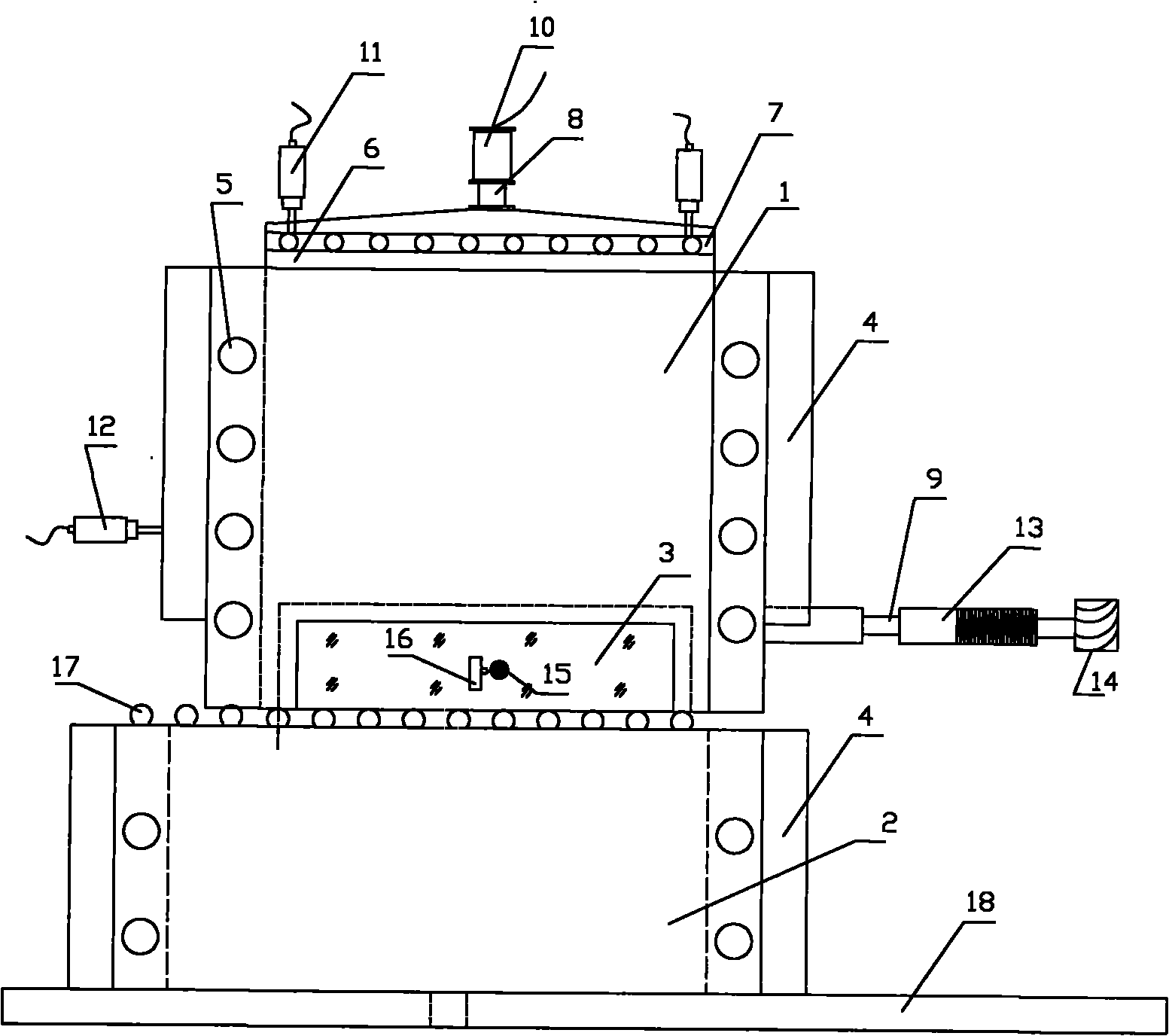
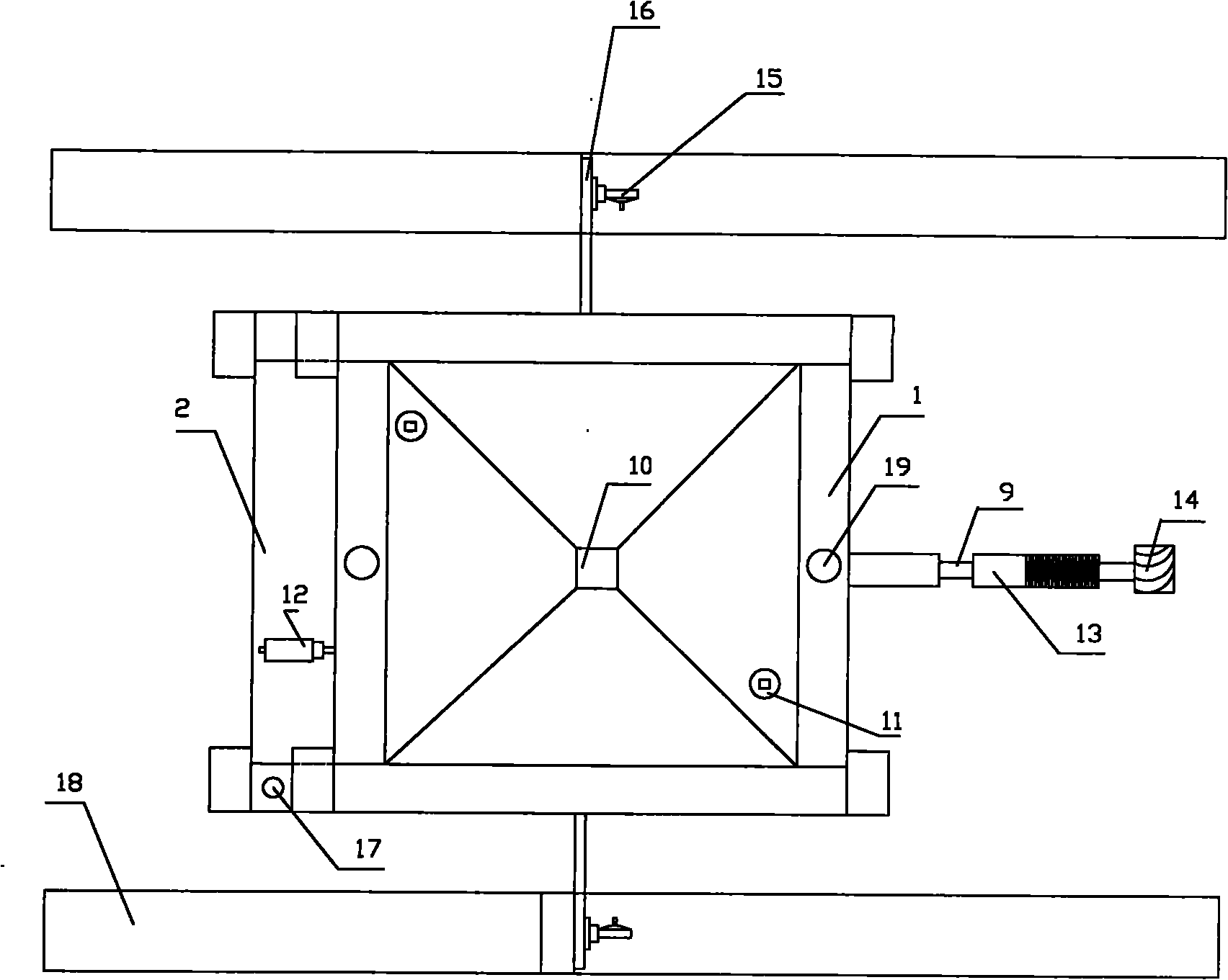
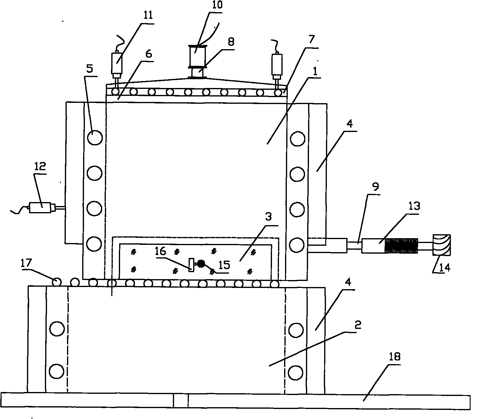
[0012] Referring to the accompanying drawings, the shear test device of the present invention consists of an outer frame 18, a horizontal and vertical loading system, a shear test visualization device, and a measurement system. The basic structure of the shear test visualization device mainly includes upper shear box 1, lower shear box 2, perspective window 3, reinforced steel plate 4, steel bolt 5, camera device 15, connecting seat 16, ball row 17; horizontal and vertical loading The system includes a square pressure bearing plate 6, a roller row 7, a jack 10, a horizontal thrust rod 13, a motor 14, and eyelet holes 19; the measuring system includes a vertical load sensor 8, a horizontal load sensor 9, a vertical displacement sensor 11, and a horizontal displacement sensor 12...


PUM


Abstract

The invention relates to an earth-structure interaction contact surface shearing test visualization device. The device mainly comprises an upper shear box (1), a lengthened lower shear box (2), a perspective window (3), a camera head (15), a connecting seat (16) and the like. The device shoots the shear band deformation and the earth grain change process in the whole shear test process by using the camera chain to acquire a series of shear band digital images at different time points and a whole-journey video, and provides references for quantitative analysis tests on the range, deformation and thickness of the earth-structure contact surface shear band. The invention has the characteristics of reasonable structure, convenient disassembly, high test load, large sample dimension, visualized shear test process, automatic data acquisition and the like, and ensures the rigidity of the shear box while realizing the overall visualized observation on the contact surface shear band. The invention can be widely used in contact surface mechanical parameter testing, and qualitative and quantitative analysis on the macroscopic and microscopic properties of the shear band under the earth-structure interaction in geotechnical engineering.

Description

technical field [0001] The invention relates to a visualization device for a contact surface shear test of soil-structure interaction, which can be widely used in rock-soil slope engineering, foundation pit protection engineering, Shear tests for underground projects such as water conservancy, hydropower and mines in moving belts. Background technique [0002] The contact problem of the interaction between soil and structure is common in geotechnical engineering, such as the contact between soil and anti-slide piles, anchor cables, retaining walls and other supporting structures in slope protection engineering, and the interlayer staggered zone in underground projects such as water conservancy and hydropower. The soil is in contact with the hard parent rock. The mechanical properties and constitutive model of the contact surface are the most important basis for the study of soil-structure interaction and support design. At present, domestic and foreign research on contact ...

Claims


Application Information

Patent Timeline
IPC IPC(8): G01N3/24G01N3/02
Inventor 李邵军陈静闵弘冯夏庭刘继光
Owner INST OF ROCK AND SOIL MECHANICS - CHINESE ACAD OF SCI
Learn More