Power module

A technology for power modules and power devices, which is applied to semiconductor/solid-state device parts, semiconductor devices, electrical components, etc., and can solve problems such as overheating of power devices

Inactive Publication Date: 2010-09-29
TOYOTA JIDOSHA KK
View PDF6 Cites 4 Cited by
  • Summary
  • Abstract
  • Description
  • Claims
  • Application Information

AI Technical Summary

Problems solved by technology

However, ordinary materials have isotropic thermal conductivity, so if the output electrode is made of a material with high thermal conductivity, a large amount of heat is also transferred between a pair of power devices
As a result, thermal interference tends to occur between a pair of power devices, and the power devices tend to overheat

Method used


Image

  • Power module
  • Power module
  • Power module

Examples


Embodiment Construction

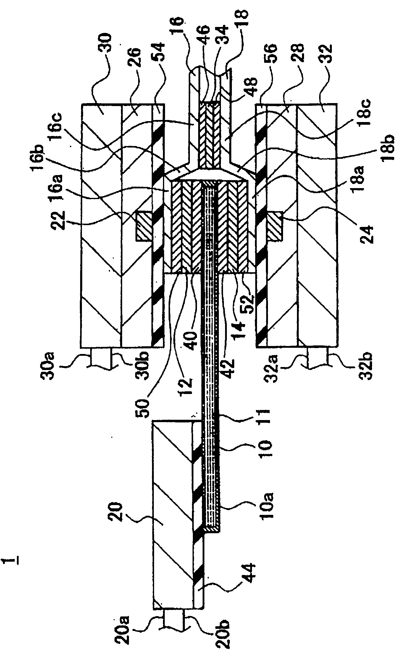
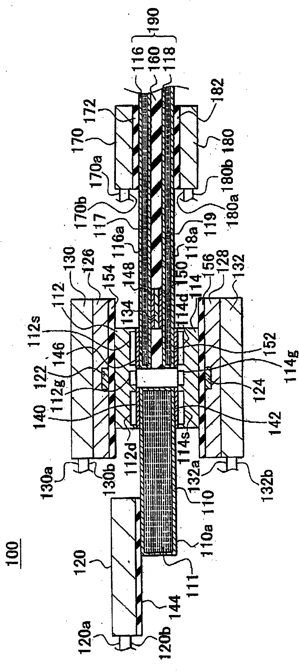
[0029] The technical features of the exemplary embodiments described below are summarized as follows.

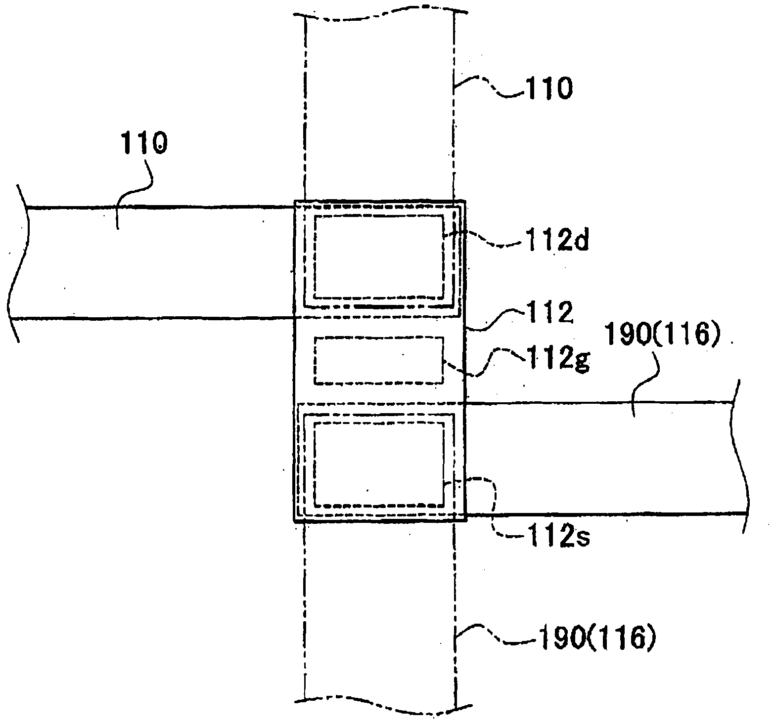
[0030] (1) Use vertical IGBTs or FETs for power devices.

[0031] (2) A plate-like self-heating tube or graphite material is used for the output electrode.

[0032] (3) The output electrode cooler is made of silicon.

[0033] (4) The N-electrode and the P-electrode are preferably arranged in parallel and facing each other, so as to effectively generate mutual inductance that reduces parasitic inductance.

[0034](5) Making the facing portion of the N electrode and the P electrode as long as possible increases the portion where the mutual inductance that reduces the parasitic inductance can be obtained, so that the two electrodes are preferably arranged facing each other from the vicinity of the power device as much as possible. close to each other.

[0035] (6) Use SrTiO 3 A sheet-type capacitor as a main component serves as a capacitor provided between an N electrode an...


PUM


Abstract

A power module includes a pair of power devices 12, 14 that are stacked with a plate-shaped output electrode arranged therebetween, and an N-electrode 16 and a P-electrode 18 that are stacked with the pair of power devices arranged therebetween. The output electrode 10 is anisotropic such that the thermal conductivity in a direction orthogonal to the stacking direction is greater than the thermal conductivity in the stacking direction. Also, the output electrode extends in the orthogonal direction from a stacked area where the pair of power devices 12, 14 are stacked. The N-electrode 16 and the P-electrode 18 extend in the orthogonal direction while maintaining an opposing positional relationship.

Description

technical field [0001] The present invention relates to a power module (power module, power module). Background technique [0002] An example of a related power module is disclosed in Japanese Patent Application Laid-Open No. 2002-26251 (JP-A-2002-26251). The power module disclosed in JP-A-2002-26251 has a pair of power devices in a state where a plate-like output electrode is provided between the pair of power devices, and N electrodes and P electrodes. stacking, the N electrode and the P electrode are stacked in a state in which the pair of power devices are disposed between the N electrode and the P electrode. The power module disclosed in JP-A-2002-26251 is advantageous in that since the N electrode, first power device, output electrode, second power device, and P electrode are stacked vertically, the entire power module can be manufactured miniaturization. [0003] If the output electrode positioned between a pair of power devices has a portion extending in an orthog...

Claims


Application Information

Patent Timeline
Patent Type & Authority Applications(China)
IPC IPC(8): H01L25/07H01L25/16H01L23/48H01L23/34H01L35/28
CPCH01L2924/13091H01L2224/73253H01L25/074H01L23/62H01L24/29H01L23/642H01L2924/19041H01L23/38H01L25/16H01L2924/30107H01L24/32H01L23/427H01L2924/13055
Inventor 山田靖长田裕司山中玄太郎古田纪文北见明朗吉田忠史久野裕道
Owner TOYOTA JIDOSHA KK
Why Eureka
Try Eureka