I2-II-IV-VI4 base thin film solar battery

A thin-film solar cell, I2-II-IV-VI4 technology, applied in circuits, electrical components, photovoltaic power generation, etc., can solve the problems of low efficiency of base thin-film solar cells, unoptimized device structure, and insufficient ohmic contact, etc. , to achieve the effects of improving light utilization efficiency, improving charge collection ability, and high photoelectric conversion efficiency

Active Publication Date: 2012-05-30
山东中科泰阳光电科技有限公司
View PDF0 Cites 0 Cited by
  • Summary
  • Abstract
  • Description
  • Claims
  • Application Information

AI Technical Summary

Problems solved by technology

cause the current I 2 -II-IV-VI 4 An important reason for the low efficiency of thin-film solar cells is that the device structure has not been optimized well. 2 -II-IV-VI 4 Insufficient ohmic contact between the base light-absorbing layer and the bottom electrode, and poor band-level matching between the buffer layer and the window layer will cause a significant decline in battery performance.

Method used


Image

  • I2-II-IV-VI4 base thin film solar battery
  • I2-II-IV-VI4 base thin film solar battery

Examples


preparation example Construction

[0023] The ZnS thin film of the window layer is usually prepared by chemical bath deposition method, sputtering method or electron beam deposition method can also be used. The thickness of the thin film of the window layer is 50nm-200nm.

[0024] The transparent conductive layer is ZnO:Al or In 2 o 3 : Sn, generally prepared by magnetron sputtering, with a thickness of 100nm to 1500nm.

[0025] The interdigitated metal electrode is a Ni / Al double-layer electrode, which is generally prepared by evaporation or sputtering, wherein the thickness of Ni is 5nm-50nm, and the thickness of Al is 500nm-2500nm.

[0026] AR coating is MgF 2 , generally prepared by evaporation method, can also be prepared by sputtering method, the thickness is 50nm ~ 500nm.

Embodiment 1

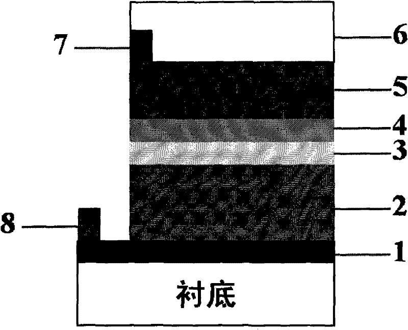
[0029] Substrate: The substrate is ordinary soda-lime glass with a thickness of 2mm.

[0030] Bottom electrode: Cu 0.5 Zn 0.5 Te / Mo double-layer composite film, prepared by magnetron sputtering method, wherein the sputtering power density of Mo is 5Wcm -2 , Cu 0.5 Zn 0.5 The sputtering power density of Te is 1.5Wcm -2 , where Mo film thickness is 800nm, Cu 0.5 Zn 0.5 The thickness of the Te film was 50 nm.

[0031] Light-absorbing layer: Cu is used for the light-absorbing layer 1.6 Zn 1.1 sn 0.9 S 1.6 Se 2.4 The preparation of the semiconductor thin film and the absorption layer adopts the co-sputtering of Cu, ZnS and SnS to prepare the precursor film with a thickness of 1000nm, and then heat-treats at 570°C for 30min in the atmosphere of S and Se to form a Cu with a thickness of 1200nm. 1.6 Zn 1.1 sn 0.9 S 1.6 Se 2.4 semiconductor film.

[0032] Buffer layer: A 20nm thick ZnS thin film and a 5nm thick SnS film were prepared on the surface of the light absorbi...

Embodiment 2

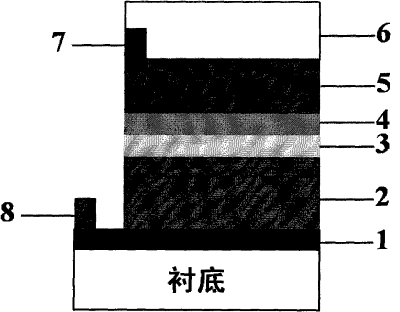
[0039] Substrate: The substrate is ordinary soda-lime glass with a thickness of 2mm.

[0040] Bottom electrode: Cu 0.6 Zn 0.4 Te / Mo double-layer composite film, prepared by magnetron sputtering method, wherein the sputtering power density of Mo is 5Wcm -2 , Cu 0.6 Zn 0.4 The sputtering power density of Te is 1.5Wcm -2 , where Mo film thickness is 1200nm, Cu 0.6 Zn 0.4 The thickness of the Te film was 20 nm.

[0041] Light-absorbing layer: Cu is used for the light-absorbing layer 1.6 ZnCd 0.1 sn 0.9 S 3.2 Se 0.8 The preparation of the semiconductor film and the absorption layer adopts the organic colloid solution method, dissolving the iodide of Cu, Zn, Cd, Sn in the organic solvent of alcohol amine multifunctional group, and then adding anhydrous ammonium sulfide and anhydrous ammonium selenide to form The organic colloid source solution of Cu, Zn, Cd, Sn, S and Se is then cast into a film, dried at 350°C for 5min and heat-treated at 580°C for 30min in an argon atm...


PUM


Abstract

The invention relates to an I2-II-IV-VI4 base thin film solar battery, which belongs to the field of new energy resources of solar batteries. The invention uses a p type I2-II-IV-VI4 base semiconductor thin film as a light absorbing layer, uses a thin film homogeneous with the light absorbing layer as a buffer layer, and optimizes the band offsets of the p-n node energy bands. A high-work-function double-layer composite thin film is used as a bottom electrode of the battery, and the contact barrier between the light absorbing layer and the bottom electrode is eliminated. A ZnS semiconductor thin film with wide band gap is used as a window layer, the light utilization efficiency of the battery is improved. The I2-II-IV-VI4 base thin film solar battery provided by the invention has the advantages of rich raw materials and low price, and has excellent device structures.

Description

technical field [0001] The present invention relates to a kind of thin film solar cell, specifically refers to a kind of 2 -II-IV-VI 4 A thin-film solar cell based on a p-type compound semiconductor thin film as a light-absorbing layer. Background technique [0002] The energy environment is closely related to the survival and development of human society. With the process of economic globalization, energy and environment issues have become urgent problems facing the whole world. The development and utilization of clean, abundant, and unrestricted solar energy is the only way to solve energy and environmental problems. Solar cells are one of the most effective forms of utilizing solar energy for human beings, and have achieved extremely rapid development in recent years. However, to realize large-scale popularization and application of solar cells and to replace traditional fossil energy as the mainstream of future energy sources, it is still necessary to vigorously devel...

Claims


Application Information

Patent Timeline
Patent Type & Authority Patents(China)
IPC IPC(8): H01L31/068H01L31/032H01L31/0224H01L31/18H01L31/06
CPCY02E10/50H01L31/0326Y02E10/547
Inventor 黄富强王耀明
Owner 山东中科泰阳光电科技有限公司
Why Eureka
Try Eureka