Optical path protecting device and method

A technology for optical path protection and protection channel, which is applied in the field of optical network communication, can solve problems such as wrong switching of working channel and protection channel, and achieve the effect of suppressing wrong switching and improving stability

Active Publication Date: 2010-09-29
北京中兴光泰软件有限责任公司
View PDF3 Cites 11 Cited by
  • Summary
  • Abstract
  • Description
  • Claims
  • Application Information

AI Technical Summary

Problems solved by technology

[0006] The problem to be solved by the present invention is to provide an optical path protection device and method to overcome the defect in the prior

Method used


Image

  • Optical path protecting device and method
  • Optical path protecting device and method
  • Optical path protecting device and method

Examples


Embodiment 1

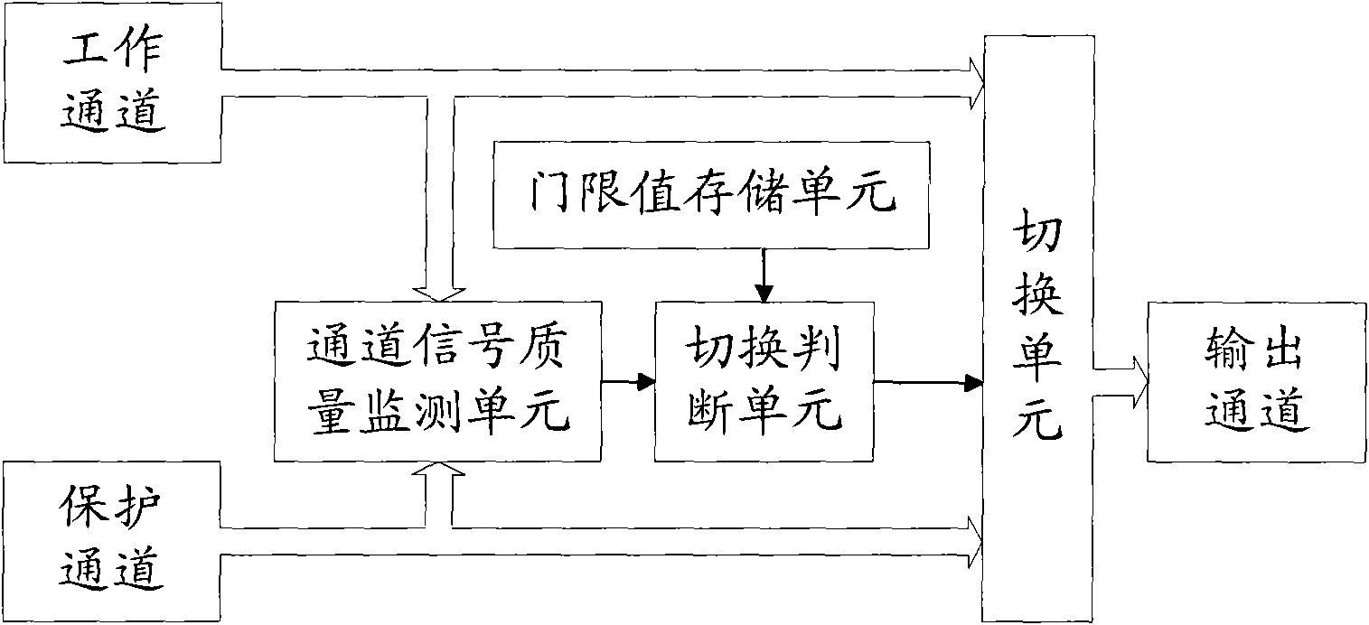
[0048] This example is in figure 1 On the basis of the optical path protection device shown, the optical path protection device of the present invention is described in detail by taking the channel signal quality determined by the optical power of the channel signal as an example. In this embodiment, the switching unit adopts an optical switch.

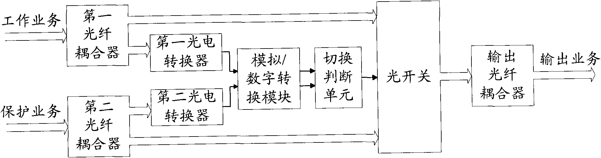
[0049] An optical path protection device in this embodiment such as image 3 As shown, the channel signal quality monitoring unit includes a first fiber coupler, a first photoelectric converter, a second fiber coupler, a second photoelectric converter and an analog / digital conversion module.

[0050] The input end of the first optical fiber coupler is connected to the optical signal of the working channel, one output end is connected to the input end of the first photoelectric converter, and the other output end is connected to an input end of the optical switch; the input end of the second optical fiber coupler One end is connected ...

Embodiment 2

[0057] This example is in figure 1 On the basis of the optical path protection device shown, the optical path protection device of the present invention will be described in detail by taking the channel signal quality determined by the bit error number of the channel signal as an example.

[0058] An optical path protection device in this embodiment such as Figure 5 As shown, the channel signal quality monitoring unit includes: a third optical fiber coupler, a third photoelectric converter, a third bit error detection module, a fourth optical fiber coupler, a fourth photoelectric converter and a fourth bit error detection module.

[0059] The input end of the third optical fiber coupler is connected to the optical signal of the working channel, and the output end is connected to the input end of the third photoelectric converter; One input end of the unit is connected; the third bit error detection module is used to calculate the bit error number of the channel signal of the...


PUM


Abstract

The invention discloses an optical path protecting device which comprises a channel signal quality monitoring unit used for monitoring the channel signal quality of a working channel and a protecting channel, a switching judging unit used for judging if to switch the working channel and the protecting channel according to the channel signal quality of the working channel and the protecting channel as well as a first absolute threshold, a second absolute threshold and a relative threshold, and a switching unit used for switching the working channel and the protecting channel according to the judgment result of the switching judging unit. The invention also discloses an optical path protecting method. The invention judges if to implement the method for switching the working channel and the protecting channel and controls the switching of the working channel and the protecting channel by comparing the channel signal quality of the working channel and the protecting channel with the preset first absolute threshold, the second absolute threshold and the relative threshold, thereby inhibiting the false switching of the working channel and the protecting channel, and improving the stability of a transmission system.

Description

technical field [0001] The invention relates to the field of optical network communication technology, in particular to an optical path protection device and method. Background technique [0002] At present, in the optical fiber communication system, in order to improve the reliability of the optical transmission system, an optical path protection device is generally used in the optical transmission system. The 1+1 or 1:1 optical fiber protection scheme is usually adopted in the transmission equipment. The optical path protection device generally has a working channel and a protection channel. Under normal working conditions, services are transmitted through the working channel. When the working channel fails, the optical path protection device switches the services to the protection channel to realize automatic service recovery. [0003] The optical path protection device judges whether the optical path is faulty by monitoring the channel signal quality, and the channel si...

Claims


Application Information

Patent Timeline
IPC IPC(8): H04B10/08H04B1/74H04B10/032H04B10/079
CPCH04B10/07953H04B10/032
Inventor 刘希琳邹红兵
Owner 北京中兴光泰软件有限责任公司
Why Eureka
Try Eureka