Aircraft landing gear

A technology of aircraft landing gear and lugs, applied in the field of aircraft landing gear, can solve the problems of inability to retract and retract, and achieve the effect of uniform force and good force effect

Inactive Publication Date: 2013-04-10
NANJING UNIV OF AERONAUTICS & ASTRONAUTICS
View PDF0 Cites 3 Cited by
  • Summary
  • Abstract
  • Description
  • Claims
  • Application Information

AI Technical Summary

Problems solved by technology

[0003] The technical problem to be solved by the present invention is to provide an aircraft landing gear, which can bypass the bulge on the fuselage to realize the retraction and retraction of the landing gear in the bulge, especially in the amphibious aircraft, to realize the retraction and retraction of the landing gear. Solve the problem that it cannot be directly retracted in the fuselage

Method used


Image

  • Aircraft landing gear
  • Aircraft landing gear
  • Aircraft landing gear

Examples


Embodiment Construction

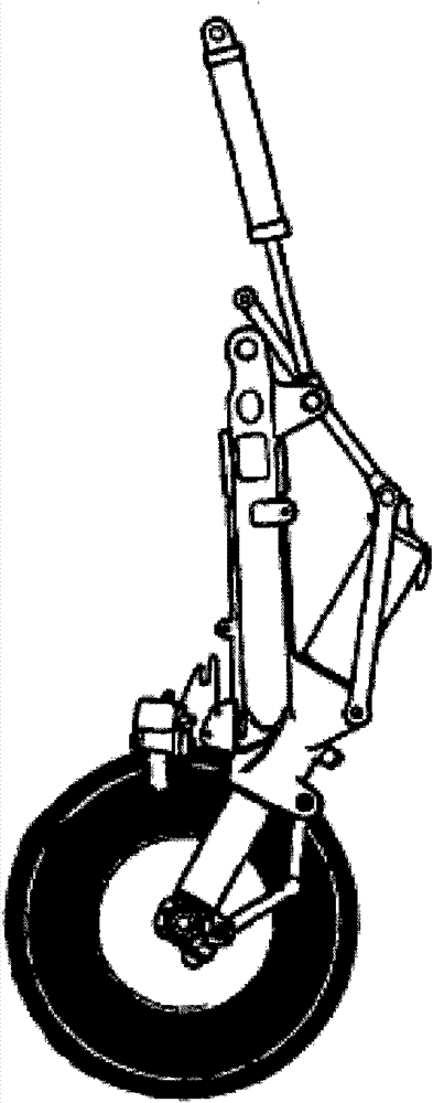
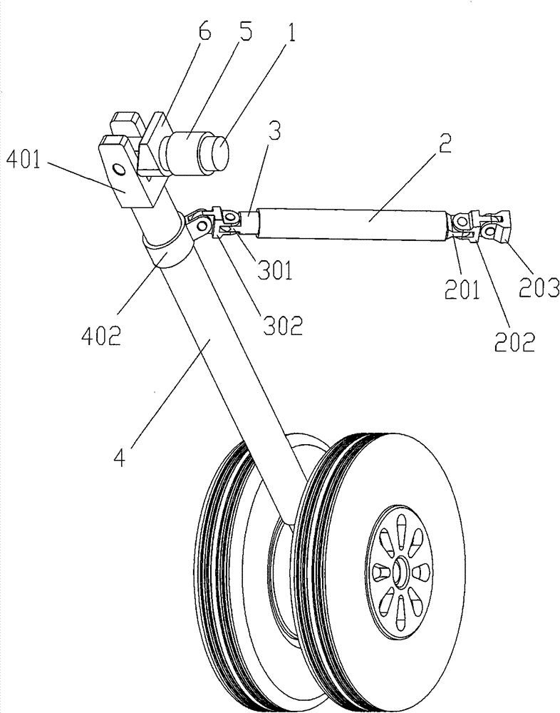
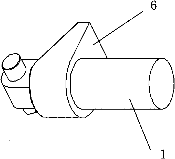
[0018] Such as figure 2 As shown, an aircraft landing gear of the present invention includes a rotating shaft 1 , an actuator 2 , a buffer 4 , a sleeve 5 , a shoulder 6 and two cross-shaped hinged lugs 202 , 302 . Sleeve 5 is fixedly connected on the fuselage. The rotating shaft 1 is located in the sleeve 5, and it is connected with the locking device. The locking control mode of the locking control device may be a common locking control mode in aircraft landing gear, such as an up lock and a down lock in the landing gear. When the locking device locks the rotating shaft 1, the rotating shaft 1 cannot rotate in the sleeve 5; when the locking device unlocks the rotating shaft 1, the rotating shaft 1 can rotate in the sleeve 5. The top end of the buffer 4 is provided with a first lug 401 , and the middle is provided with a second lug 402 . The rotating shaft 1 is embedded in the first lug 4 , and there is a gap between the first lug 4 and the rotating shaft 1 . The rotating...


PUM


Abstract

The invention relates to an aircraft landing gear, which comprises a rotating shaft, an actuating cylinder and a buffer. A piston rod is sleeved in the actuating cylinder, the rotating shaft is provided with a sleeve which is fixedly connected on a fuselage; the top end of the buffer is provided with a first lug plate and the middle part of the buffer is provided with a second lug plate; the rotating shaft is positioned in the first lug plate and is connected with the first lug plate by a pin and the buffer can take rotating motion around the pin; the rotating shaft between the first lug plate and the sleeve is provided with a shaft shoulder which is in inclined state toward one side of the first lug plate; the aircraft landing gear also comprises two cross hinged lug plates; the lug plates on the actuating cylinder are connected with lug plates on the fuselage by the cross hinged lug plates; and a lug plate on the piston rod is connected with the second lug plate on the buffer by thecross hinged lug plate. Due to the adoption of the technical scheme, by movement of the piston rod in the actuating cylinder and control of a locking control device for the rotating shaft, the aircraft landing gear can realize movement of the landing gear in the three-dimensional space and guarantee that the landing gear can move around a bulge on the fuselage to be retracted successfully.

Description

technical field [0001] The present invention relates to a kind of spare parts of flying device, in particular, relates to a kind of landing gear of aircraft, comprises rotating shaft, actuating cylinder and buffer, and piston rod is set in actuating cylinder, and one end of this actuating cylinder and piston rod One end of each is provided with an ear piece. Background technique [0002] At present, the way of retracting and retracting the landing gear of the flight usually adopts the method of directly retracting and retracting. as attached figure 1 As shown, the landing gear includes a rotating shaft, an actuator, a buffer and a retractable rod, and a piston rod is sleeved in the actuator, and one end of the actuator and one end of the piston rod are provided with lugs. The rotating shaft is fixedly connected on the fuselage, and the retractable rod is respectively hinged with the piston rod and the buffer. The piston rod can move in the cylinder. The movement of the p...

Claims


Application Information

Patent Timeline
Patent Type & Authority Patents(China)
IPC IPC(8): B64C25/02
Inventor 魏小辉詹家礼龙双丽
Owner NANJING UNIV OF AERONAUTICS & ASTRONAUTICS
Why Eureka
Try Eureka