
Bridge girder erection machine capable of passing through tunnel and realizing girder erection and bridging process thereof

A bridge erecting machine and tunnel technology, which is applied in the field of new bridge erecting machines for passing tunnels and tunnel opening beams, can solve the problems of low construction efficiency, high stability of guide beams, unable to complete the opening beam erection, etc., and achieve stable operation, The effect of high construction efficiency

Active Publication Date: 2010-10-06
CHINA RAILWAY ENG MACHINERY RES & DESIGN INST +1
View PDF4 Cites 23 Cited by
  • Summary
  • Abstract
  • Description
  • Claims
  • Application Information

AI Technical Summary

Problems solved by technology

[0013] 1. The above 1 and 3 cannot complete the opening of the beam;
[0014] 2. The above 1, 2, and 3 all need to be disassembled to pass through the tunnel;
[0015] 3. The construction efficiency of the above 4 is very low, and the guide beam requires high stability

Method used


Image

  • Bridge girder erection machine capable of passing through tunnel and realizing girder erection and bridging process thereof
  • Bridge girder erection machine capable of passing through tunnel and realizing girder erection and bridging process thereof
  • Bridge girder erection machine capable of passing through tunnel and realizing girder erection and bridging process thereof

Examples


Embodiment Construction

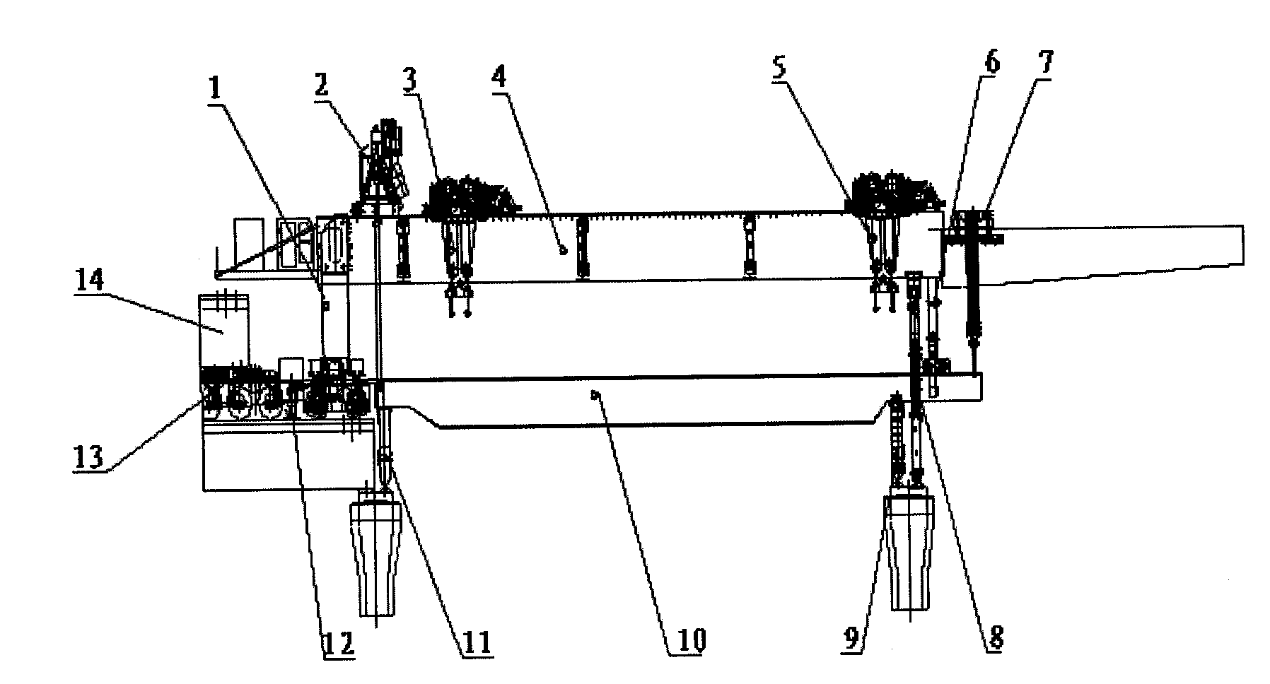
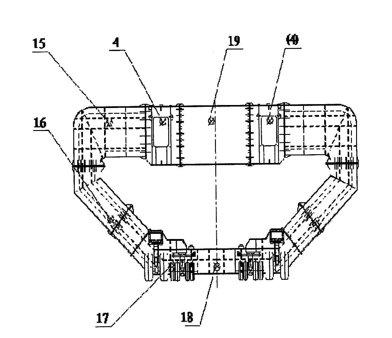
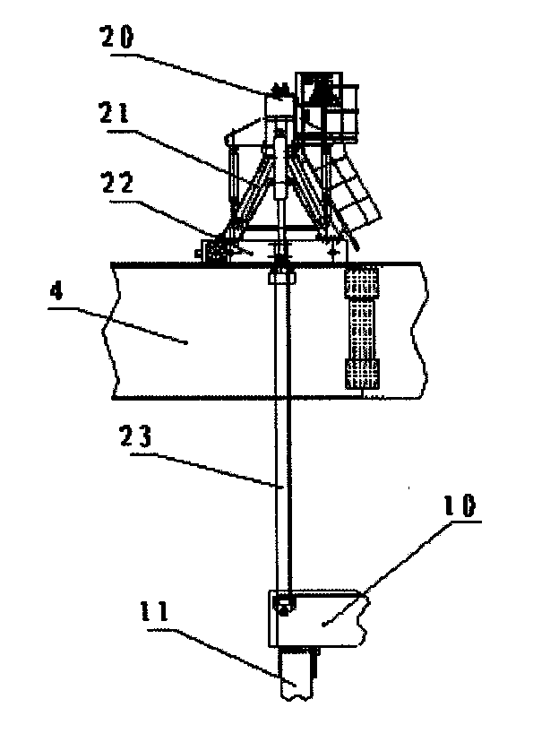
[0050] refer to figure 1 According to the present invention, the bridge erecting machine capable of passing through a tunnel and realizing beam erection at the tunnel entrance mainly includes a main engine and a lower guide beam 10 . Described main engine comprises main beam 4 and from the back end of main beam 4 to the front end (so-called front and back is that the beam erecting direction is the front, vice versa) is installed with rear outrigger 1, rear guide beam crane 2, rear lifting Heavy trolley 3, front hoisting trolley 5, front outrigger 8, auxiliary walking outrigger 6, leading beam crane 7. A track is arranged on the main girder 4, and the front lifting trolley 5, the rear lifting trolley 6, the front guide beam crane 7 and the rear guide beam crane 2 run on the track. The lower guide beam 10 includes the main beam of the lower guide beam, the rear outrigger 11 located at the rear and lower side thereof, and the front outrigger 9 located at the front lower side. D...


PUM


Abstract

The invention relates to a bridge girder erection machine capable of passing through a tunnel and realizing girder erection and a bridging process thereof. The bridge girder erection machine comprises a mainframe and a lower guide beam, the mainframe comprises a main beam, and also comprises a rear ground jack, a rear guide beam overhead travelling crane, a rear crane trolley, a front crane trolley, a front ground jack, an auxiliary travelling ground jack and a front guide beam overhead travelling crane which are arranged successively from the rear end to the front end of the main beam; a track is arranged on the main beam, and the front crane trolley, the rear crane trolley, the front guide beam overhead travelling crane and the rear guide beam overhead travelling crane run on the track; the lower guide beam comprises a main beam of the lower guide beam, a rear ground jack arranged behind the lower part of the main beam, and a front ground jack arranged in front of the lower part of the main beam; the bridge girder erection machine and the bridging process can realize bridge girder erection and beam erection operations in mountain areas; a mode of mixed beam taking by the crane trolleys of the bridge girder erection machine, a beam transporting vehicle and a pack trolley can realize beam erection at a tunnel portal; and when passing a tunnel, a plurality of components can be retracted and folded to enable the bridge girder erection machine to pass through the channel conveniently without being limited by the diameter of the tunnel, and the bridging construction efficiency is high and the bridging operation is stable.

Description

technical field [0001] The invention relates to a bridge erecting machine capable of passing through tunnels and erecting girders at tunnel entrances, in particular to a bridge erecting device for rapid construction in mountainous areas, and in particular to a new bridge erecting machine for passing through tunnels and erecting beams at tunnel entrances. Background technique [0002] With the further strengthening and development of my country's infrastructure, the construction of various infrastructures is entering a rapid and steady development stage. The "Eleventh Five-Year Plan" of railways shows that China's railways have entered a stage of leapfrog development, especially since the economic crisis. my country has increased investment in infrastructure such as railways and highways, and railway construction will reach an unprecedented peak. As my country's railway construction enters a stage of continuous and rapid development, a key problem to be solved in the aspect of...

Claims


Application Information

Patent Timeline
IPC IPC(8): E01D21/00
Inventor 王光欣张智莹党春太李晓钢林承朝罗璞
Owner CHINA RAILWAY ENG MACHINERY RES & DESIGN INST
Learn More