Supercharge Your Innovation With Domain-Expert AI Agents!

H-shaped shaft flood discharge hole

A technology of flood tunnels and shafts, which is applied in the field of flood tunnels, can solve problems such as unstable water flow transitions, prone to hydraulic jumps in flood tunnels, and affecting the safe operation of flood tunnels, so as to ensure safe operation, realize water flow, and safe connection Effect

Inactive Publication Date: 2011-11-30
SICHUAN UNIV
View PDF0 Cites 0 Cited by
  • Summary
  • Abstract
  • Description
  • Claims
  • Application Information

AI Technical Summary

Problems solved by technology

[0002] The unpressurized flow in the open channel with high water head and large flow is introduced into the submerged flood discharge tunnel through the shaft, in essence, the water flow transitions from the unpressurized internal flow discharge facility (shaft) to the pressurized internal flow facility (spill tunnel), so the water flow Unfavorable hydraulic phenomena such as hydraulic jumps are prone to occur in the flood discharge tunnel, which affects the safe operation of the flood discharge tunnel.
In the existing technology, through the structural improvement of the shaft (for example, designing the shaft as a double-vortex aeration type swirl shaft), setting a pressure slope at the exit of the shaft can stabilize the flow state of the water flow and improve the cavitation and cavitation damage of the spillway. However, it is still difficult to solve the safety threat to the flood tunnel due to the unfavorable water flow pattern caused by the hydraulic jump in the cave and the accumulation of air bags caused by the flooding of the flood tunnel outlet.

Method used


Image

  • H-shaped shaft flood discharge hole
  • H-shaped shaft flood discharge hole
  • H-shaped shaft flood discharge hole

Examples


Embodiment 1

[0021] The water retaining structure of a water conservancy project adopts a concrete gravity dam, the maximum dam height is 210m, and the discharge capacity of the spillway tunnel is 1350m 3 / s, has the characteristics of narrow river valley, high water head, large flow and high velocity.

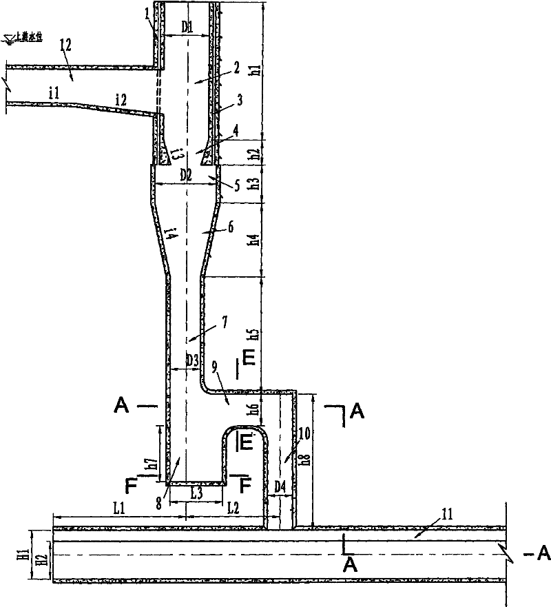
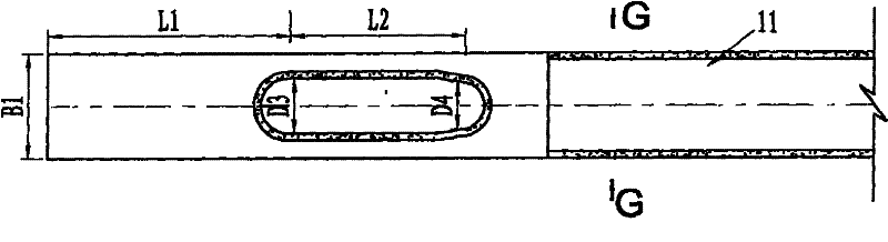
[0022] In this embodiment, the structure of the h-shape shaft spillway is as follows figure 1 , figure 2 As shown, it consists of a "city gate hole" shaped flood discharge tunnel 11 and a shaft connected to the flood discharge tunnel arranged at the closed end of the flood discharge tunnel. The shaft includes a first shaft 1 and a second shaft 10; the first shaft 1 is double The vortex-chamber air-mixed swirl shaft is located above the spillway, and its centerline intersects vertically with the centerline of the spillway, its upper part is connected to the water flow diversion channel 12, and its lower end is closed; The centerlines are parallel, the upper end is closed, and the lower e...

Embodiment 2

[0036] The water retaining structure of a water conservancy project adopts a concrete gravity dam, the maximum dam height is 180m, and the discharge capacity of the spillway tunnel is 570m 3 / s, has the characteristics of narrow river valley, high water head, large flow and high velocity.

[0037] In this embodiment, the structure of the swirl shaft submerged flood discharge tunnel is the same as that in Embodiment 1, as figure 1 , figure 2 Shown, difference with embodiment 1 is the size of each part, relevant size is as follows:

[0038] The relevant dimensions are as follows:

[0039] 1. Lead the canal

[0040] The slope i1 of the water inlet section I = 1:22, and the slope i2 of the water inlet section II of the diversion channel = 1:12.

[0041] 2. The first shaft - double vortex chamber aeration type swirl shaft

[0042] The diameter of the upper vortex chamber D1=10m, the height of the upper vortex chamber h1=40m, the height of the contraction section of the upper vo...


PUM


Abstract

The invention relates to an h-shaped shaft flood discharge hole comprising a flood discharge hole and a shaft, wherein the shaft is arranged at the closed end of the flood discharge hole and communicated with the flood discharge hole and comprises a first shaft and a second shaft; the first shaft is positioned above the flood discharge hole, the centre line of the first shaft is vertically intersected with that of the flood discharge hole, the upper part of the first shaft is connected with a water flow approach channel, and the lower end of the first shaft is closed; the centre line of the second shaft is parallel to that of the first shaft, the upper end of the second shaft is closed, and the lower end of the second shaft is connected and communicated with the top of the flood dischargehole; the first shaft is communicated with the second shaft through a joint segment; and the first shaft and the second shaft are combined into an h-shaped outline. The first shaft of the h-shaped shaft flood discharge hole is a double-volute chamber air entraining type swirling shaft.

Description

technical field [0001] The invention belongs to the field of flood discharge tunnels of water conservancy and hydropower projects, and in particular relates to a submerged vertical shaft flood discharge tunnel used under the conditions of high water head, large flow rate and from no-pressure flow to pressurized flow. Background technique [0002] The unpressurized flow in the open channel with high water head and large flow is introduced into the submerged flood discharge tunnel through the shaft, in essence, the water flow transitions from the unpressurized internal flow discharge facility (shaft) to the pressurized internal flow facility (spill tunnel), so the water flow Unfavorable hydraulic phenomena such as hydraulic jumps are prone to occur in the flood discharge tunnel, which affects the safe operation of the flood discharge tunnel. In the existing technology, through the structural improvement of the shaft (for example, designing the shaft as a double-vortex aeration...

Claims


Application Information

Patent Timeline
Patent Type & Authority Patents(China)
IPC IPC(8): E02B8/06E02B9/06
CPCY02E10/22Y02E10/20
Inventor 张建民许唯临刘善均王韦曲景学邓军李忠任成瑶陈剑刚李进胡晓禹
Owner SICHUAN UNIV
Features
  • R&D
  • Intellectual Property
  • Life Sciences
  • Materials
  • Tech Scout
  • Unparalleled Data Quality
  • Higher Quality Content
  • 60% Fewer Hallucinations
Learn More