
Balanced valve and crane using same

A technology for balancing valves and valve cores, applied in cranes, mechanical equipment, fluid pressure actuation devices, etc., to solve problems such as damage to hydraulic components, user discomfort, structural vibration and noise

Active Publication Date: 2012-11-21
XUZHOU HEAVY MASCH CO LTD
View PDF0 Cites 0 Cited by
  • Summary
  • Abstract
  • Description
  • Claims
  • Application Information

AI Technical Summary

Problems solved by technology

However, since there is no transition stage when the spring force pushes the steel ball to close the channel, the control oil is suddenly blocked, so the liquid flowing in the pipeline will form a high pressure peak and produce a hydraulic shock, making the valve of the balance core The core commutation process cannot be carried out smoothly
[0004] As we all know, hydraulic shock will cause damage to hydraulic components, and even bring unpredictable hydraulic failure and safety hazards; in addition, the vibration and noise of structural parts caused by hydraulic shock during use have brought a lot of discomfort to users

Method used


Image

  • Balanced valve and crane using same
  • Balanced valve and crane using same
  • Balanced valve and crane using same

Examples


Embodiment Construction

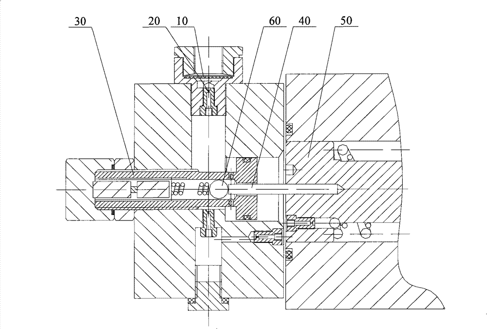
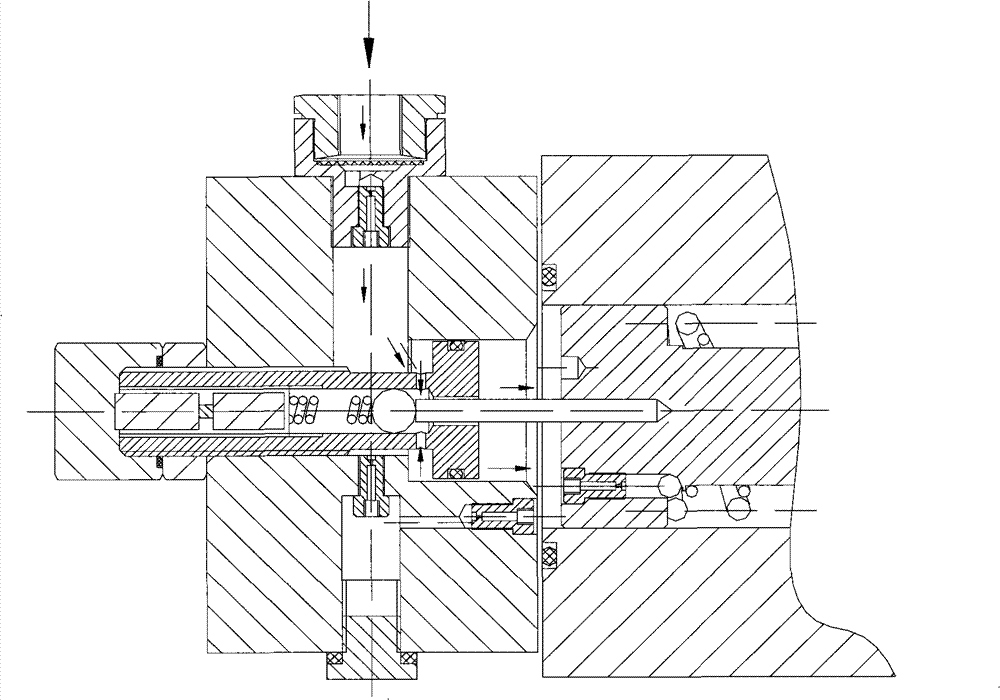
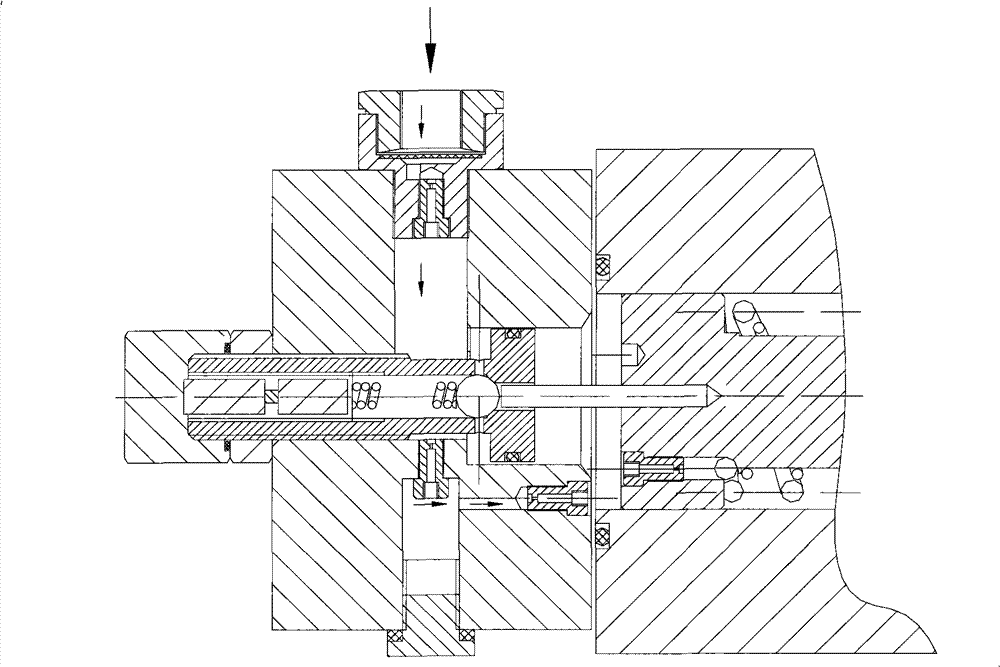
[0031] Based on the prior art, there are two control oil passages between the control oil port of the valve body of the balance valve provided by the present invention and the chamber at the end of the spool, and the first oil passage has a plugging component and is linked with the spool. The ejector rod; the control oil enters the chamber through the hole between the ejector rod and the first oil passage, and the plugging part moves with the ejector rod and after the end of the plug seals the hole, the control oil The liquid enters the chamber through the second oil passage; the key point of the design is that there is a throttling groove on the end mating surface of the plugging part matched with the hole, and the cross-sectional area of ​​the throttling groove is along the The axial direction gradually decreases, so that when the mating surface gradually approaches the pore until it is blocked, the flow rate through the pore decreases gradually, so as to avoid hydraulic shoc...


PUM


Abstract

The invention discloses a balanced valve. Two control oil ducts are arranged between the control oil port of a valve body and a chamber at the end part of a valve core; control oil acts on the valve core through the two control oil dusts to realize the reversing of the valve core; a plugging part is matched with the hole of the first oil dust to close the first oil dust; a throttling groove is arranged on the end part, which is matched with the hole, of the plugging part; and the cross sectional area of the throttling groove gradually reduces along the axial direction, so that the through flow passing through the hole is slowly reduced in the process that the matched surface and the hole become closer gradually and then are plugged, thus larger pressure shock can not be generated at the moment of closing the first oil dust. Preferably, a valve core reverse control loop is provided with a hydraulic half bridge composed of a relief valve and a damp, because the pressure and the flow actin a coupling mode, and a signal output by aiming at the flow grain or the pressure gain can be stably transited to a steady-state value. The invention also provided with a crane using the balanced valve.

Description

technical field [0001] The invention relates to a hydraulic control element, in particular to a balance valve and a crane using the balance valve. Background technique [0002] Cranes are widely used in various engineering constructions. At present, with the development of technology and the improvement of users' requirements for crane operation, the optimal design of cranes should not only meet the basic main functions, but also pay more and more attention to the safety and reliability requirements of crane operations and the comfort requirements of operation. [0003] In the control system of main functions such as lifting, luffing and telescoping of existing cranes, balance valves are used for hydraulic locking to ensure that the load can be reliably kept at any position and avoid displacement due to internal leakage of hydraulic components. Usually, when the balance valve is opened in the forward direction, the hydraulic oil directly pushes the check valve in the valve ...

Claims


Application Information

Patent Timeline
Patent Type & Authority Patents(China)
IPC IPC(8): F15B13/02B66C23/62
Inventor 刘邦才冯文昌徐尚国
Owner XUZHOU HEAVY MASCH CO LTD
Learn More