Brake clutch

A clutch device and clutch technology, applied in the field of clutches, can solve the problems that affect the processing quality, trouble equipment manufacturers and operators, and the depth of tapping or drilling cannot be accurately controlled.

Inactive Publication Date: 2012-05-23
李世民
View PDF0 Cites 0 Cited by
  • Summary
  • Abstract
  • Description
  • Claims
  • Application Information

AI Technical Summary

Problems solved by technology

[0009] The loosening and coupling of the clutch 15 is achieved by tightening the plate friction. Since the frictional resistance of this structure is small, it is often unable to meet the processing requirements of high-torque power transmission such as general tapping or drilling, resulting in To make the friction surface at the plate prone to slipping, resulting in work interruption and shutdown, so the work efficiency is quite limited
[0010] After the clutch 15 is used for a period of time, it will wear obviously, resulting in a reduction in the torque transmission efficiency, making the above-mentioned slipping phenomenon more serious, so the service life is short, and it is necessary to replace the clutch frequently, and the cost of parts replacement is high.
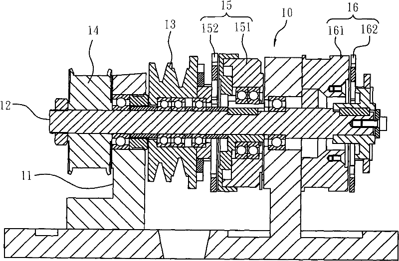
[0011] The power interruption of the transmission shaft 12 is achieved by closing the clutch 15 and then starting the brake 16. Therefore, the power interruption time of the transmission shaft 12 will be affected by the length of the demagnetization time of the clutch 15 electromagnet 151. Generally speaking, If the degaussing time point is at the higher peak position of the current sine wave, a longer degaussing time is usually required; on the contrary, at the lower peak position, the required degaussing time is naturally shortened. Such a situation will cause power interruption. The response time is different, so in the above-mentioned tapping or drilling operations, the depth of tapping or drilling often cannot be accurately controlled, resulting in unstable processing accuracy and affecting the processing quality
[0012] The power transmission of the power transmission shaft 12, that is, when it is desired to perform processing operations, must first close the brake 16 to remove the braking state of the transmission shaft 12, and then start the clutch 15 for power transmission. However, as mentioned above, when the brake 16 When it is closed, its electromagnet 161 needs a period of demagnetization time, but before the complete demagnetization, that is, before the braking state of the transmission shaft 12 is completely released, the clutch 15 has usually started to perform power transmission, so it often causes the brake 16 to be demagnetized. The closing of the clutch 15 and the starting action of the clutch 15 cannot be smoothly connected. In such a situation, unnecessary friction loss will be caused between the plates on the clutch 15 and the brake 16, and the wear will be accelerated.
In the same way, when the power transmission of the drive shaft 12 is interrupted, that is, when the machining stroke ends, the clutch 15 must be closed first to interrupt the power transmission, and then the brake 16 is started to automatically return the tapping or drill bit. However, the clutch The electromagnet 151 of 15 also needs a period of degaussing time. Before it is completely demagnetized, the brake 16 is usually activated. Acceleration to wear the pad
[0013] The power transmission of the power transmission shaft 12 is mainly driven by the clutch plate on the clutch 15 and the clutch disc 152 with surface contact and mutual pressing friction. The time will also be extended accordingly, making the processing accuracy poorer, and the actions between the above-mentioned clutch 15 and brake 16 will not be able to smoothly connect with each other, causing the above-mentioned problems to become more serious
[0014] The above shortcomings have plagued equipment manufacturers and operators for a long time, but there is no suitable and effective technical solution

Method used


Image

  • Brake clutch
  • Brake clutch
  • Brake clutch

Examples


Embodiment Construction

[0080] see Figure 2 to Figure 5 As shown, the present invention is a first embodiment of a brake and clutch device. The brake and clutch device 1 mainly includes a wheel-shaped transmission part 20, two bearings 30, a shaft-shaped transmission part 40, two ratchet assemblies 50, and a plurality of engaging parts. Column 60, an occlusal column push-out device 70, and a ratchet brake device 80; the following is a separate description of the above-mentioned components.

[0081] Regarding the wheel-shaped transmission member 20, it mainly includes a body 20a and a limiting ring 20b; wherein:

[0082] The main body 20a is a pulley in this embodiment, and its outer peripheral wall is provided with two pulley grooves 21, which can be driven by a belt driven by a motor; one end side of the main body 20a is provided with a screw hole 22, and the screw hole 22 A circular groove 23 is recessed in the center of the bottom wall of the hole, and a bearing accommodation groove 24 is recess...


PUM


Abstract

The invention relates to a brake clutch, comprising a wheel-shaped driving part, a shaft-shaped driving part, two ratchet assemblies, a snap-in column pushing-off device and a ratchet brake apparatus. The wheel-shaped driving part comprises a clutch chamber and a snap-in wall; the shaft-shaped driving part is mutually pivoted with the wheel-shaped driving part; the two ratchet assemblies are contained and limited in the clutch chamber and comprise a fixed ratchet assembly which is mutually connected with the shaft-shaped driving part and a moveable ratchet assembly which can freely rotate on the shaft-shaped driving part, the peripheral walls of the ratchet assemblies are respectively equipped with a plurality of opposite ratchets, and a column-containing groove is limited between any twoopposite ratchets so that a plurality of snap-in columns can be selectively configured and limited in the groove; the snap-in column push device is used for pushing the snap-in columns to abut with the snap-in wall so that the wheel-shaped driving part and the shaft-shaped driving part can generate a power transmission action; and the ratchet brake apparatus is used for limiting the moveable ratchet assembly to rotate so that the snap-in columns are separated from the snap-in wall to stop the power transmission action, and meanwhile the shaft-shaped driving part is locked by a brake. By the structures, the brake clutch can achieve good brake clutch control and power transmission effect.

Description

technical field [0001] The present invention is related to a clutch, more specifically, a brake clutch device. Background technique [0002] Existing many power mechanical equipments, especially processing machinery equipments such as automatic lathes, are often equipped with electromagnetic brake clutch devices, so as to control the output of power, and when the power output stops, the transmission shaft is braked and locked. [0003] Such as figure 1 As shown, there is disclosed a brake clutch seat 10 that can be installed on an automatic lathe and equipped with an electromagnetic brake clutch device to provide power transmission control required for machining operations such as tapping or drilling. [0004] The clutch 10 includes a fixed seat 11, on which a transmission shaft 12 is mounted and pivoted, on which a belt pulley 13 that can be driven by the motor, and an output pulley 14 connected to the transmission shaft 12 are pivotally provided. The above-mentioned elec...

Claims


Application Information

Patent Timeline
Patent Type & Authority Patents(China)
IPC IPC(8): F16D67/02F16D65/12F16D65/02
Inventor 李世民
Owner 李世民
Why Eureka
Try Eureka