Devices for rotary stamping

A technology for adjusting devices and rollers, which is applied in the direction of rotary printing machines, printing machines, printing machines, etc., and can solve problems such as strong vibrations, gap size changes, and stability limitations of stamping devices.

Inactive Publication Date: 2018-01-19
WINK STANZWERKZEUGE +1
View PDF6 Cites 0 Cited by
  • Summary
  • Abstract
  • Description
  • Claims
  • Application Information

AI Technical Summary

Problems solved by technology

These changes can reach up to 10 -6 m range and thus lead to an undesired change in the size of the gap
Furthermore, due to its hollow-cylindrical design, the counter-pressure cylinder can vibrate strongly, the forces occurring here being absorbed by the bearings, which can lead to increased wear and possibly less accurate punching patterns
Due to the hollow design, the stability of the punching unit is limited

Method used


Image

  • Devices for rotary stamping
  • Devices for rotary stamping
  • Devices for rotary stamping

Examples


Embodiment Construction

[0024] Individual technical features of the embodiments described below can likewise be combined in combination with the previously described embodiments as well as features of the dependent claims and possible further claims relative to the object according to the invention.

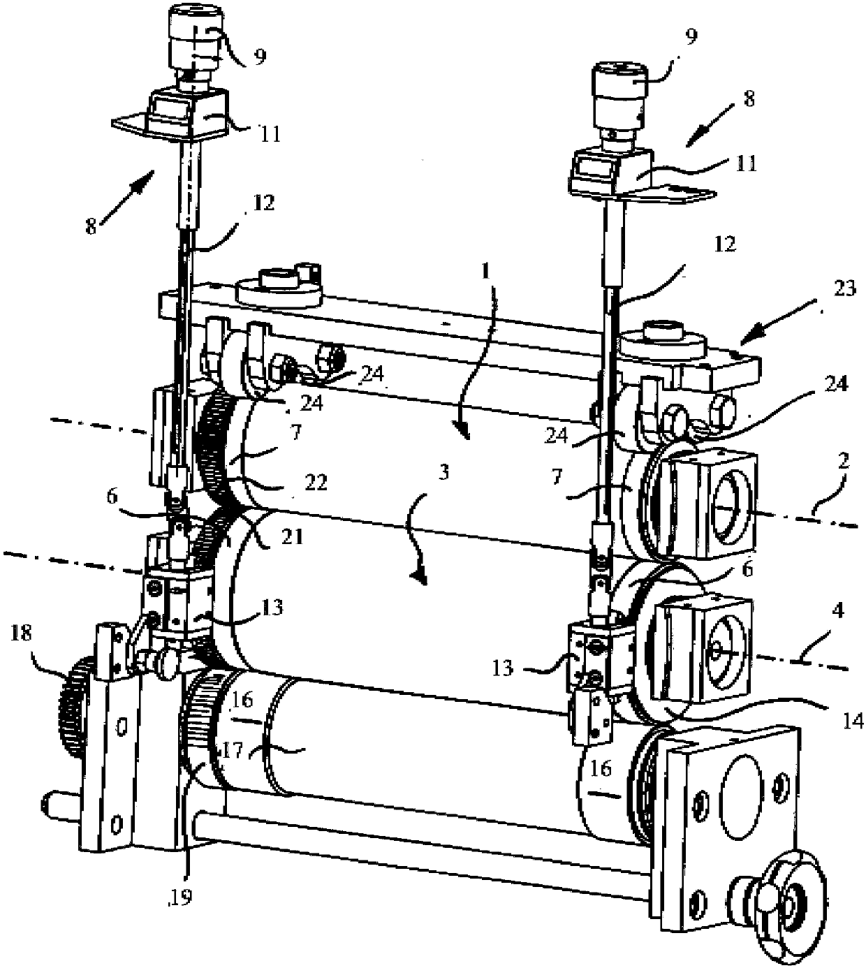
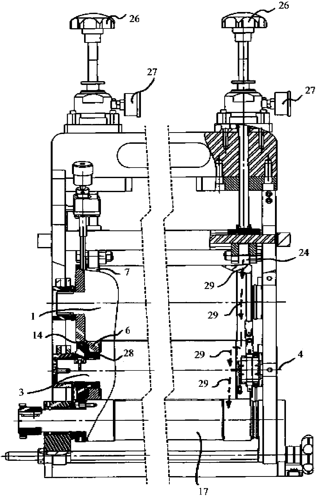
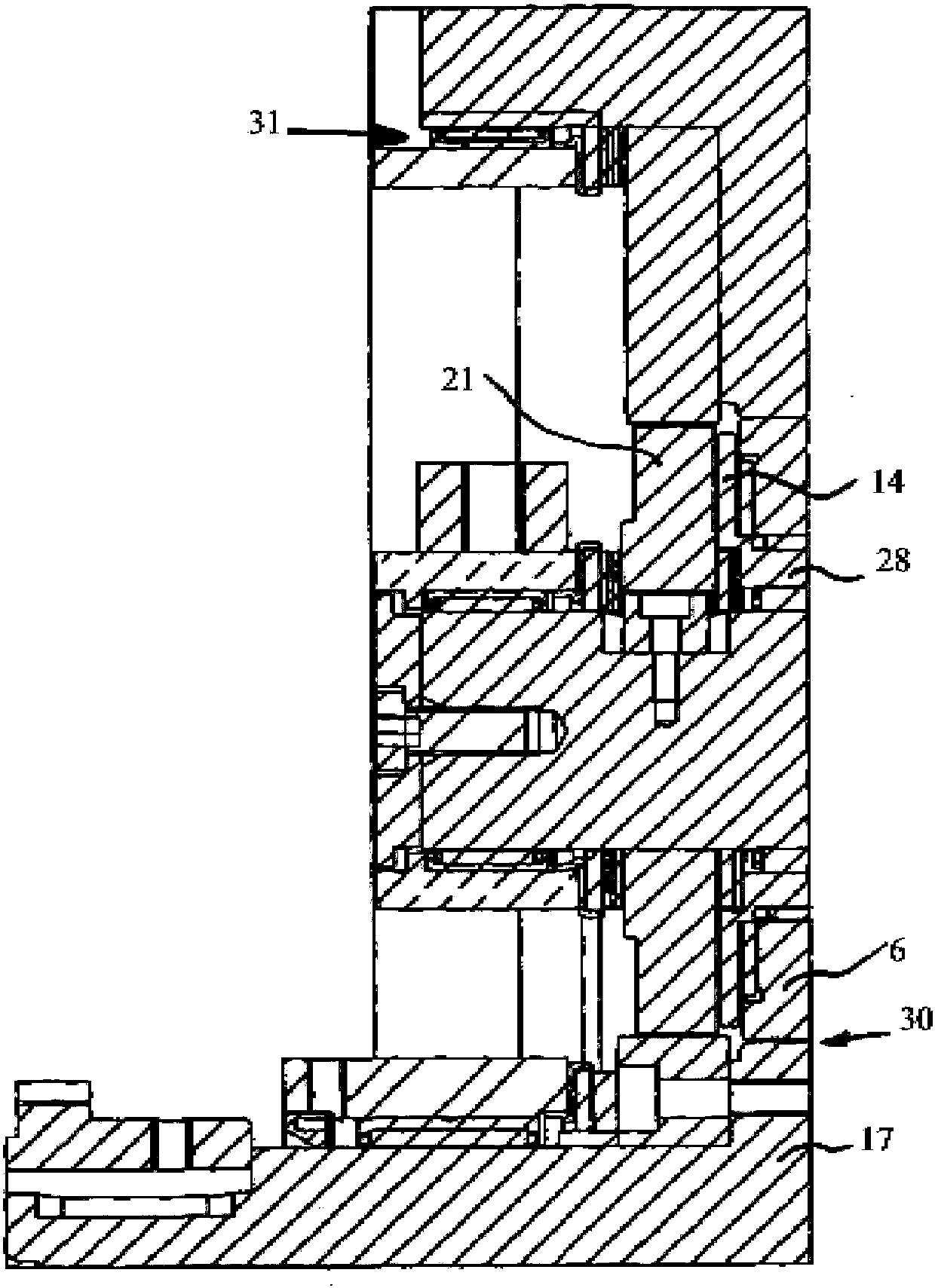
[0025] The device according to the invention for rotary stamping according to figure 1 A stamping cylinder 1 is provided which is arranged rotatably about a stamping cylinder axis 2 . Furthermore, the device has a counterpressure roller 3 which is rotatable about a counterpressure roller axis 4 . The counter-pressure cylinder 3 has a running ring 6 on which the running surface 7 of the punching cylinder 1 runs. These running surfaces 7 can be part of a separately produced stamping cylinder raceway or can be formed in one piece with the stamping cylinder body. Furthermore, the rotary punching device has an adjusting device, by means of which the size of the gap between the punching cylinder 1 and the c...


PUM


Abstract

Device for rotary punching with a punching drum (1) rotatable about a punching drum axis (2), with a counter-pressure drum (3) rotatable about a counter-pressure drum axis (4), wherein the counter-pressure The roller (3) has a running ring (6) on which the punching roller (1) or its punching roller ring can run on the running surface (7) and with an adjustable positioning between the punching roller and the counter-pressure roller ( 1,3) Adjusting device for the size of the gap with a further roller, wherein the further roller is configured as a support shaft (17) on which the counter-pressure roller (3) is directly supported.

Description

technical field [0001] The invention relates to a device for rotary stamping with a stamping cylinder rotatable about the axis of the stamping cylinder and with a counter-pressure cylinder rotatable about the axis of the counter-pressure cylinder, wherein the counter-pressure cylinder has a stamping cylinder or its stamping cylinder A rolling ring, on which the rolling ring can run, with an adjustment device by means of which the size of the gap between the stamping cylinder and the counter-pressure cylinder can be adjusted, with a further roller. Background technique [0002] An object according to the preamble of claim 1 is described in EP 580576 B1. The heat generated by vibrations or impacts towards the counterpressure roller and mechanical loads in the bearings is dissipated from the raceways only via the racetracks of the counterpressure roller or via the bearings of the counterpressure roller. In this case, slight variations in the dimensions of the raceways may occu...

Claims


Application Information

Patent Timeline
Patent Type & Authority Patents(China)
IPC IPC(8): B26D7/26B26F1/38
CPCB26D7/265B41F19/008B26D7/2628B26F1/384B31B50/14B31B2100/00
Inventor 乔尔·博特隆
Owner WINK STANZWERKZEUGE
Why Eureka
Try Eureka