Flange assembly machine

An assembly machine and flange technology, applied in auxiliary devices, auxiliary welding equipment, welding/cutting auxiliary equipment, etc., can solve the problems of no positioning steel pipe, poor fixation, and reduced flange assembly effect, saving human resources and saving Human and material resources, saving the effect of producing finished products

Active Publication Date: 2015-04-29
江苏振光电力设备制造有限公司
View PDF6 Cites 22 Cited by
  • Summary
  • Abstract
  • Description
  • Claims
  • Application Information

AI Technical Summary

Problems solved by technology

The flange assembly method disclosed in this invention patent is a simple assembly method, without automatic operation mode, poor fixation, and not suitable for use in spot welding devices
And there is no operation method for positioning the steel pipe fixing function, so the accuracy of flange installation on the pipe cannot be guaranteed, which reduces the flange assembly effect

Method used


Image

  • Flange assembly machine
  • Flange assembly machine
  • Flange assembly machine

Examples


Embodiment Construction

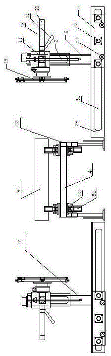
[0040]As shown in the figure, a flange assembly machine includes an adjustment mechanism 01 and a pipeline delivery mechanism 02; the adjustment mechanism 01 is located on both sides of the pipeline delivery mechanism 02, and the adjustment mechanism 01 is based on the pipeline delivery mechanism 02 Axis of symmetry, distributed symmetrically from left to right;

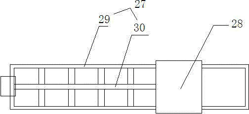
[0041] The adjustment mechanism 01 includes a horizontal displacement mechanism 27 and a grasping mechanism 28. The horizontal displacement mechanism 27 includes a base 29 and a telescopic pull rod 30. The base 29 is a rectangular parallelepiped frame structure, and the two sides of the base 29 are respectively provided with A sliding engagement channel 31, the telescopic end of the telescopic pull rod 30 is fixed on the grasping mechanism 28;

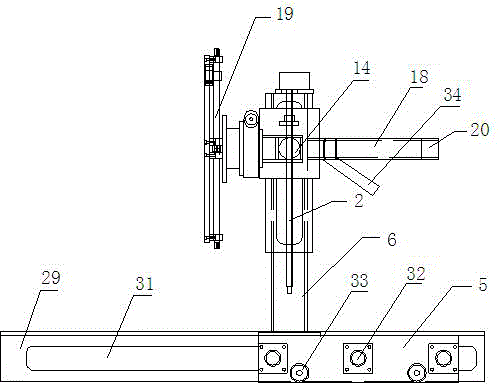
[0042] The grabbing mechanism 28 includes a main frame 1, a lifting device 2, a grabbing device 3 and a flange fixing plate 4, the main frame 1 includes a base 5 and a frame ...


PUM


Abstract

The invention relates to a flange assembly machine. The flange assembly machine comprises a pipeline transporting mechanism, and regulating mechanisms which are positioned at the two sides of the pipeline transporting mechanism and are symmetrically distributed left and right by taking the pipeline transporting mechanism as an axis of symmetry; when a pipeline transporting device transports a pipeline to an assembly position, the regulating mechanisms grip a flange and transport the flange to the two sides of the pipeline, so that the flange and the pipeline are aligned and fitted with each other and are finally welded into an integer; when the pipeline assembly is ended, the pipeline transporting device operates for transporting away the assembled pipeline. The flange assembly machine is convenient to operate, fully automatic and intelligent in operation in the whole process, and relatively safe and reliable, greatly saves manpower and material resources, and reduces production cost.

Description

technical field [0001] The invention relates to a flange assembly machine. Background technique [0002] The assembly flanges in the prior art are all manually assembled, the degree of automation is low, and the efficiency is low, the assembly accuracy is very low, and there is a huge potential safety hazard. [0003] Chinese patent CN200820037771.8 discloses a flange assembly device, which includes a control cabinet, on which a chuck that can fix the flange is installed. The chuck is provided with three stepped tooth-shaped claws for fixing the flange, and the plane of the chuck is perpendicular to the ground. The flange assembly method disclosed in this invention patent is a simple assembly method without automatic operation mode, poor fixation, and is not suitable for use in spot welding devices. And there is no operation mode for positioning the fixing function of the steel pipe, so the accuracy of flange installation on the pipeline cannot be guaranteed, which reduces...

Claims


Application Information

Patent Timeline
Patent Type & Authority Applications(China)
IPC IPC(8): B23K37/04B23K37/00
CPCB23K37/00B23K37/04
Inventor 贾红宝黄国焕李代君蒋胜利张桂宝
Owner 江苏振光电力设备制造有限公司
Why Eureka
Try Eureka